Automatic buoy drilling device for fishing gear

A drilling device and float technology, which is applied in metal processing and other directions, can solve the problems of float damage, lower production efficiency, easy injury, etc., and achieve the effect of reducing hazards

Active Publication Date: 2021-06-29
临湘骑乐钓具有限公司
View PDF5 Cites 0 Cited by
  • Summary
  • Abstract
  • Description
  • Claims
  • Application Information

AI Technical Summary

Problems solved by technology

[0004] In order to overcome the disadvantages that the float is easily damaged, the production efficiency is reduced, and the hands are easily injured due to the manual failure to hold the float in the process of manual drilling. Float automatic drilling device for fishing tackle

Method used


Image

  • Automatic buoy drilling device for fishing gear
  • Automatic buoy drilling device for fishing gear
  • Automatic buoy drilling device for fishing gear

Examples


Embodiment 1

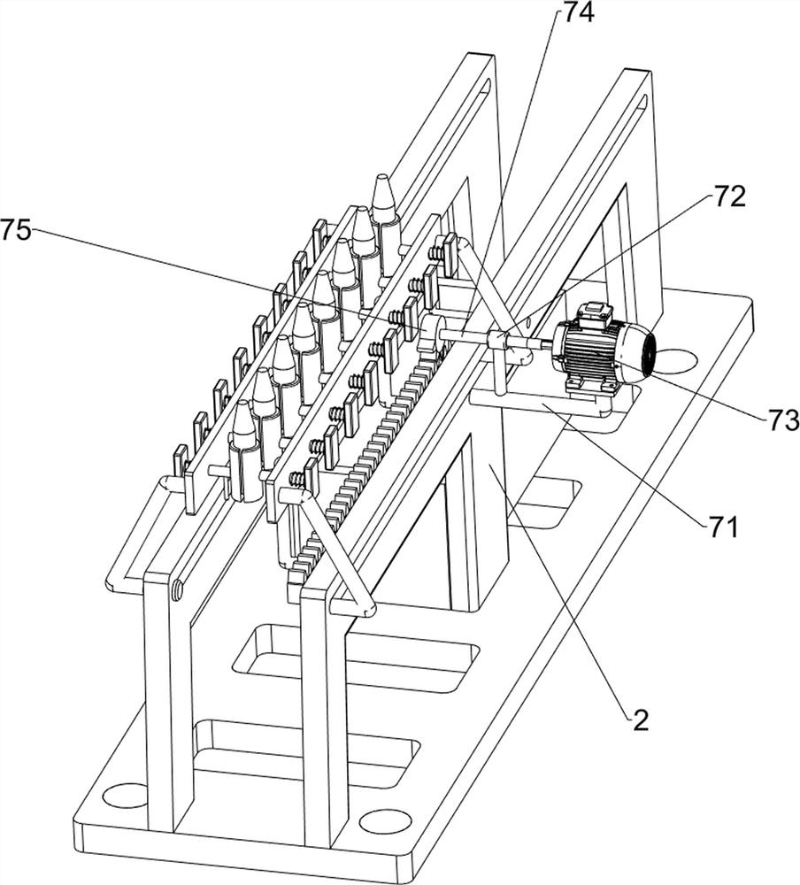
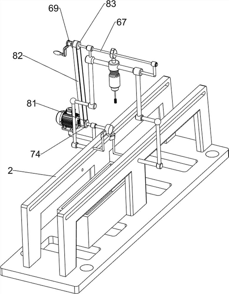
[0027] A floating automatic drilling device for fishing gear, such as figure 1 As shown, it includes a base 1, a support column 2, a collector 3, a feeding mechanism 4, a clamping mechanism 5 and a drilling mechanism 6. The top of the left and right sides of the base 1 is provided with a support column 2, and the top of the front side of the base 1 is provided with The collector 3 is provided with a feeding mechanism 4 between the rear sides of the two supporting columns 2 , a drilling mechanism 6 is provided between the middle outer walls of the two supporting columns 2 , and a clamping mechanism 5 is provided on the feeding mechanism 4 .

[0028] When people need to drill the fishing gear float, they can use this fishing gear float automatic drilling device. First, people need to put the float in the 5 parts of the clamping mechanism, and then manually rotate the 6 parts of the drilling mechanism to make the drilling mechanism The 6 parts can drill the clamped floats. When o...

Embodiment 2

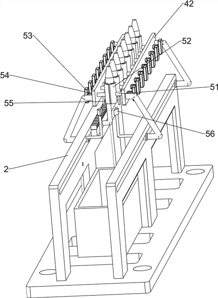
[0030] On the basis of Example 1, such as Figure 2-7 As shown, the feeding mechanism 4 includes a fixed bracket 41, a baffle plate 42 and a rack 43, and the rear sides of the support columns 2 on the left and right sides are slidingly symmetrically provided with a fixed bracket 41, and between the fixed brackets 41 on the left and right sides, a fixed bracket 41 is arranged. A baffle 42 is arranged, and the inner wall of the baffle 42 on the left side is provided with a rack 43 .

[0031] After people clamp the float in the clamping mechanism 5, they push the fixed bracket 41 forward on the support column 2, and the fixed bracket 41 drives the baffle plate 42 to move forward, thereby driving the clamped float to move forward and make it move Drilling is carried out at the drilling mechanism 6, the baffle plate 42 drives the rack 43 to move forward, and after the drilling is completed, the fixing bracket 41 is pushed backward to make it reset.

[0032] The clamping mechanism ...


PUM


Abstract

The invention relates to a drilling device, in particular to an automatic buoy drilling device for a fishing gear. The invention provides an automatic buoy drilling device for a fishing gear, which is capable of drilling automatically, wide in application field and capable of preventing the buoy from being damaged. An automatic buoy drilling device for a fishing gear comprises a base, supporting columns, a collector, a feeding mechanism, a drilling mechanism, a clamping mechanism and the like, wherein the supporting columns are arranged on the tops of the left side and the right side of the base, the collector is arranged on the top of the front side of the base, the feeding mechanism is arranged between the rear sides of the two supporting columns, the drilling mechanism is arranged between the outer walls of the middles of the two supporting columns, and the clamping mechanism is arranged on the feeding mechanism. According to the automatic buoy drilling device disclosed by the invention, a sliding block is pulled to slide towards the outer side, a second spring is compressed, the sliding block drives a second sliding rod to slide towards the outer side, so that clamps are driven to move outwards in a back-to-back mode, then the buoy is placed between the clamps, and therefore, effect of clamping the buoy can be achieved.

Description

technical field [0001] The invention relates to a drilling device, in particular to a floating automatic drilling device for fishing gear. Background technique [0002] With the continuous improvement of people's living standards, more and more people like outdoor leisure activities. Leisure activities can adjust and relax our body and mind. Fishing has become one of the outdoor activities that people love. Fishing can exercise people's mind and improve fishing quality. The attention of the fisherman, exercise their patience, the float will transmit the information of the fish swallowing the bait, when the fish swallows the bait on the hook, the position of the hook will change and be transmitted to the float, the float also has the function of indicating the position of the hook In the small-scale fishing gear float processing factory, the float is usually drilled manually using simple tools. During the manual drilling process, because the float is not held firmly manually,...

Claims


Application Information

Patent Timeline
Patent Type & Authority Applications(China)
IPC IPC(8): B26F1/16B26D7/02B26D7/06B26D7/18B26D5/02
CPCB26F1/16B26D7/02B26D7/0616B26D7/18B26D5/02B26D2007/0018
Inventor 不公告发明人
Owner 临湘骑乐钓具有限公司
Why Eureka
Try Eureka