Suspension seeder for wet ground

A suspension type, seeder technology, applied in the field of seeder, can solve the problems of low seed germination rate, seed exposure, inability to absorb nutrients, etc.

Active Publication Date: 2021-12-21
赤峰市淇艺机械有限责任公司
View PDF8 Cites 0 Cited by
  • Summary
  • Abstract
  • Description
  • Claims
  • Application Information

AI Technical Summary

Problems solved by technology

[0005] The purpose of the present invention is to solve the lack of a strong structure that will cover the upper surface of the seeds in the existing seeders in the prior art. When the seeder sows the seeds into the soil, the soil covering the upper surface of the seeds is less or even appears. Most of the seeds are exposed to the air. In this case, the seeds cannot absorb nutrients from enough soil, which eventually leads to the problem of low germination rate of the seeds sown by the planter. A suspended sowing method for wet ground is proposed machine

Method used


Image

  • Suspension seeder for wet ground
  • Suspension seeder for wet ground
  • Suspension seeder for wet ground

Examples


Embodiment 1

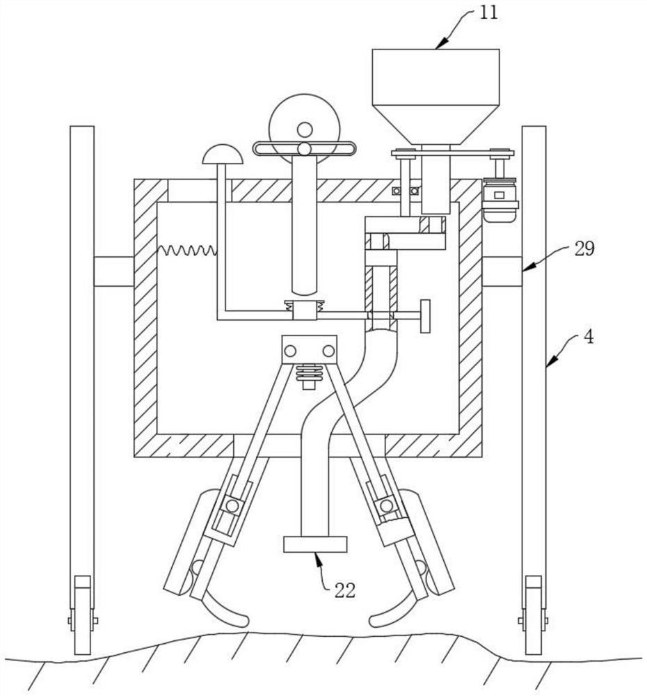
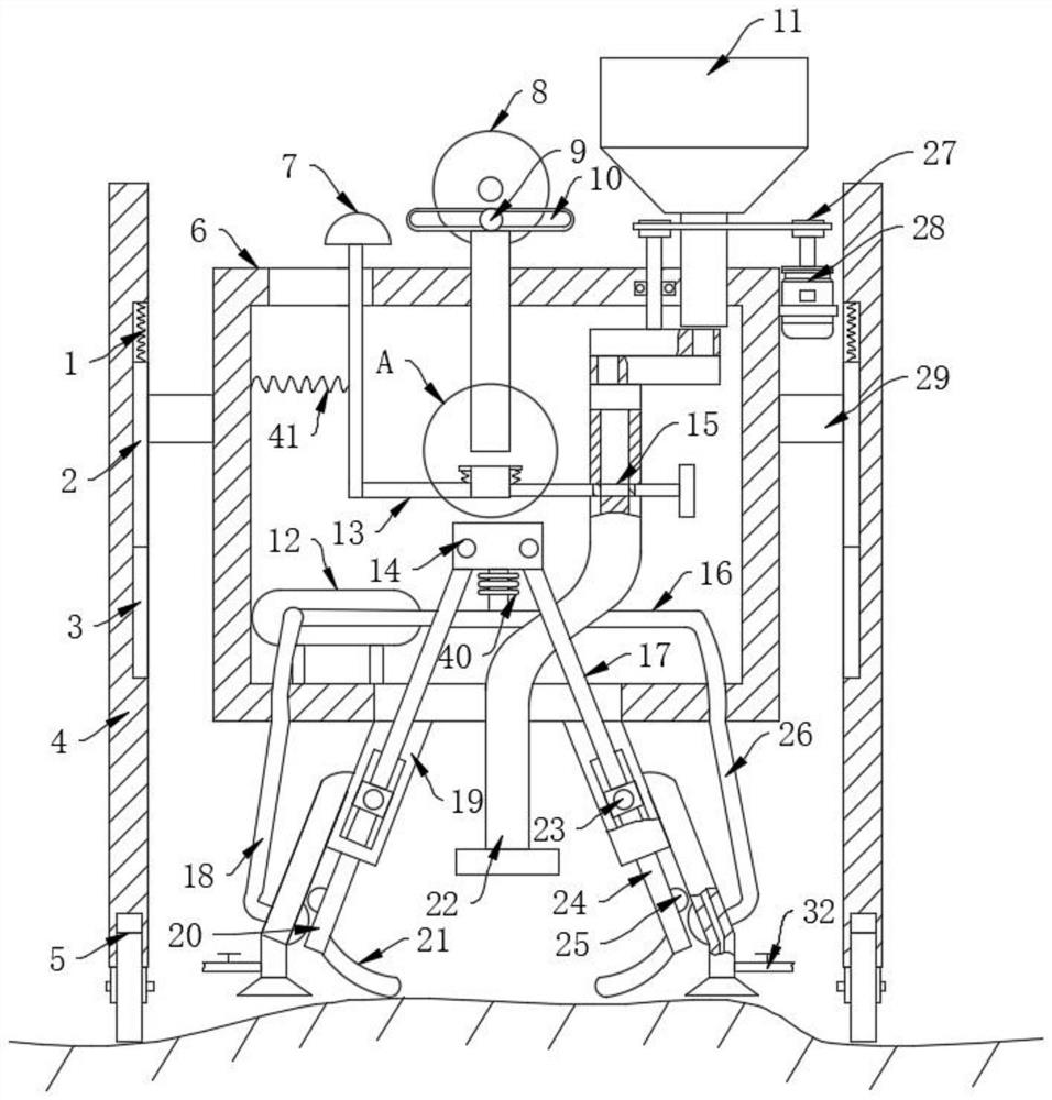
[0030] refer to figure 1 , image 3 , Figure 4 , Figure 5 , a suspension type seeder for wet ground, comprising a walking frame 4, the bottom of the walking frame 4 is rotatably connected with a walking wheel 5, one side of the top of the walking frame 4 is fixedly connected with a first connecting block 29, and one side of the first connecting block 29 is fixed Connected with the housing 6, the middle position of the top of the housing 6 is fixedly connected with the driving wheel 8, and one side of the end surface of the driving wheel 8 is fixedly connected with the driving pin 9, and the driving pin 9 is slidably connected with the U-shaped block 10 along the end surface of the driving wheel 8.

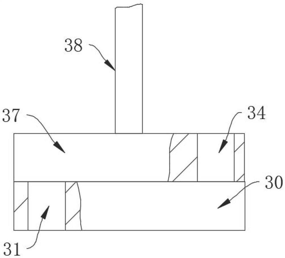
[0031] The bottom of the U-shaped block 10 is fixedly connected with a push rod 33, one side of the top of the housing 6 is fixedly connected with a storage bucket 11, and the side of the housing 6 is fixedly connected with a rotating shaft 38 by the side of the storage bucket ...

Embodiment 2

[0037] refer to figure 2 , different from Embodiment 1, the top of the walking frame 4 is fixedly connected with the second connecting spring 1, and the walking frame 4 is provided with a chute 3 near the second connecting spring 1, the length of the chute 3 is greater than the length of the slide bar 2, and the second The bottom of the connection spring 1 is fixedly connected with the slide bar 2, the slide bar 2 slides in the chute 3, the side of the slide bar 2 is fixedly connected with the first connection block 29, and the walking frame 4 is provided with the chute 3 at the position of the second connection spring 1 , the length of the chute 3 is greater than the length of the slide bar 2, the bottom of the housing 6 is fixedly connected with an air pump 12, and the outlet end of the air pump 12 is fixedly connected with a left air injection pipe 18 and a right air injection pipe 26, and the air pump 12 passes through the left air injection pipe 12 and the right air injec...


PUM


Abstract

The invention discloses a suspension seeder for wet ground, relates to the field of seeder technology, and comprises a walking frame, the bottom of the walking frame is rotatably connected with traveling wheels, and a connecting block is arranged on one side of the top of the walking frame. When the present invention pushes the push block to drive the cushion block that is slidably connected in the middle of the connecting flap along the vertical direction to move to the top of the drive block, at this time, the drive wheel drives the push rod to push the drive block downward through the mutual cooperation of the drive pin and the U-shaped block, The downward movement of the driving block forces the bottom of the sliding slanting rod to rotate through the connecting block, and the arc-shaped dial at the bottom of the connecting rod rotates under the action of the protrusion and the driven protrusion, so as to cover the upper surface of the seed with enough soil to prevent the occurrence When the machine sows the seeds into the soil, the soil covering the upper surface of the seeds is less and even most of the seeds are exposed to the air. In this case, the seeds cannot absorb nutrients from enough soil.

Description

technical field [0001] The invention relates to the technical field of seeders, in particular to a suspension seeder for wet ground. Background technique [0002] Seeder is a planting machine that takes crop seeds as the sowing object. The seeder used for a certain type or a certain crop is often named after the type of crop, such as grain drill, corn hole seeder, cotton seeder, pasture spreader, etc. According to the sowing method, it can be divided into the following types. Folding sowing machine: a sowing machine that distributes the scattered seeds evenly on the sowing plot. The commonly used model is a centrifugal spreader, which is attached to the rear of the agricultural transport vehicle. Consists of a seed box and a spreading wheel. Seeds fall from the seed box to the spreading wheel, and are broadcast along the tangential direction under the action of centrifugal force; folded drill type: mainly used for sowing small seeds such as grains, vegetables, pastures, e...

Claims


Application Information

Patent Timeline
Patent Type & Authority Patents(China)
IPC IPC(8): A01C5/00A01C7/18
CPCA01C5/00A01C7/18
Inventor 成惠
Owner 赤峰市淇艺机械有限责任公司
Why Eureka
Try Eureka