Thread end knotting device, thread winding system and thread end knotting method
A knotting device and thread end technology, which is applied in the directions of transportation and packaging, delivery of filamentous materials, thin material processing, etc., can solve the problems of unable to load the winding machine and reduce processing efficiency, so as to reduce manual intervention and improve utilization rate , Improve the effect of processing efficiency
- Summary
- Abstract
- Description
- Claims
- Application Information
AI Technical Summary
Problems solved by technology
Method used
Image
Examples
Embodiment 1
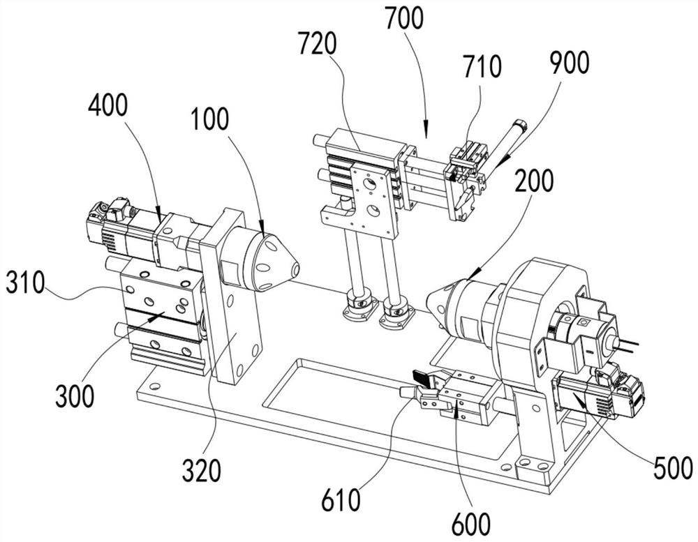
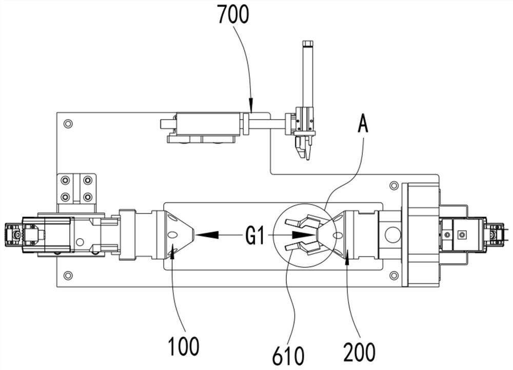
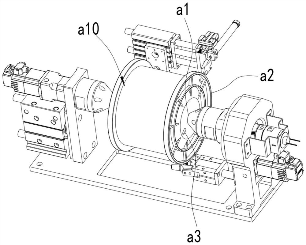
[0085] The thread end knotting device disclosed by the present invention will be described below in conjunction with the accompanying drawings, as shown in the attached figure 1 As shown, it includes a drive shaft 100 and a driven shaft 200 coaxially arranged on the placement table 1000 with gaps. The size of the word wheel is designed so that the I-shaped wheel can be suspended and fixed between them.
[0086] as attached figure 1 As shown, the driving shaft 100 and / or the driven shaft 200 are driven by the axial driving mechanism 300 to move axially, the driving shaft 100 is connected to the first driving mechanism 400 that drives its rotation, and the driven shaft 200 An automatic jaw 600 driven by the second drive mechanism 500 to revolve around the driven shaft 200 is arranged on the outer periphery, and the chuck 610 of the automatic jaw 600 faces the driving shaft 100 and extends to the end of the driven shaft 200 A certain distance in front, said distance is determin...
Embodiment 2
[0110] In the above-mentioned embodiment 1, the method of manual loading and unloading is adopted, but the weight of the full line wheel is relatively large, and it is inefficient and labor-intensive to manually load the material and fix the thread end on the thread end grasper, so it is more labor-intensive. The best way is to use automatic equipment for loading and unloading and place the thread end between the two jaws of the thread end gripper.
[0111] as attached Figure 11 , attached Figure 12 As shown, in this embodiment, the above functions are realized by the loading and unloading robot b. The wire wheel grabbing device b1 of the wire wheel, the moving mechanism b2 for driving the wire wheel grabbing device b1 to move, and the wire between the wire wheel and the wire pay-off frame e1 of the winding machine e before they are disconnected The wire end gripper b3 between the wire clamps.
[0112] Specifically, as attached Figure 13 As shown, the wire wheel grabbin...
Embodiment 3
[0124] In the above-mentioned embodiment 2, the wire between the full-line wheel and the pay-off frame e1 is manually cut off, or the gripper and the thread-cutting mechanism provided at the winding machine or the pay-off frame are used to realize the connection between the full-line wheel and the wire-cutting frame. The cutting of the wire between the pay-off frames e1.
[0125] as attached Figure 11 As shown, in this embodiment, the fuse of the wire and the clamping of the wire end on one side of the pay-off frame are realized by setting the automatic wire breaking mechanism d. Specifically, the automatic wire breaking mechanism d is set on the substrate c and is located between the placing table 1000 and the loading and unloading robot b, which is close to the placing table 1000 .
[0126] as attached Figure 16 As shown, the automatic disconnection mechanism d includes a mounting frame d100, and a fuse d200 is arranged on the vertical plate d110 of the mounting frame d1...
PUM
 Abstract
Description
Claims
Application Information
 - R&D
- Intellectual Property
- Life Sciences
- Materials
- Tech Scout
- Unparalleled Data Quality
- Higher Quality Content
- 60% Fewer Hallucinations
Browse by: Latest US Patents, China's latest patents, Technical Efficacy Thesaurus, Application Domain, Technology Topic, Popular Technical Reports.
© 2025 PatSnap. All rights reserved.Legal|Privacy policy|Modern Slavery Act Transparency Statement|Sitemap|About US| Contact US: help@patsnap.com


