Supercharge Your Innovation With Domain-Expert AI Agents!

A foundation pit support structure and its construction method

A foundation pit support and support plate technology, which is applied in infrastructure engineering, excavation, construction, etc., can solve problems such as easy blockage of support pipe suction holes and affect drainage effects, and achieve the effect of maintaining drainage efficiency and facilitating cleaning

Active Publication Date: 2022-04-22
福建中骏长鑫建工有限公司
View PDF6 Cites 0 Cited by
  • Summary
  • Abstract
  • Description
  • Claims
  • Application Information

AI Technical Summary

Problems solved by technology

[0004] In view of the above-mentioned related technologies, the inventor believes that in the above scheme, the support pipe is inserted into the soil, and the soil, silt, etc. in the soil layer can easily block the water absorption holes on the support pipe, thereby affecting the drainage effect

Method used


Image

  • A foundation pit support structure and its construction method
  • A foundation pit support structure and its construction method
  • A foundation pit support structure and its construction method

Examples


Embodiment 1

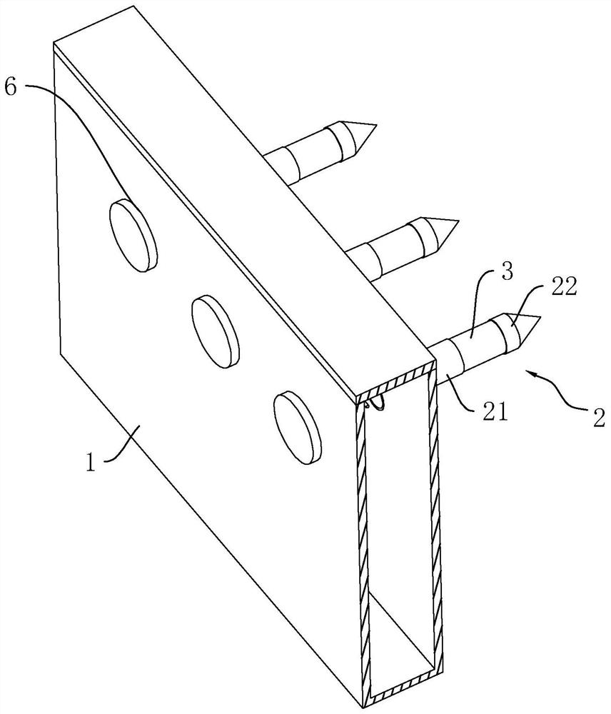
[0040] refer to figure 1 , the support structure of the foundation pit includes an inner hollow support plate 1, a drainpipe 2 is installed on one side of the support plate 1, there are multiple drainpipes 2, and the drainpipe 2 communicates with the inner cavity of the support plate 1, The drain pipe 2 can be plugged into the soil, and the water in the soil can enter the support plate 1 through the drain pipe 2 and then be drained away.

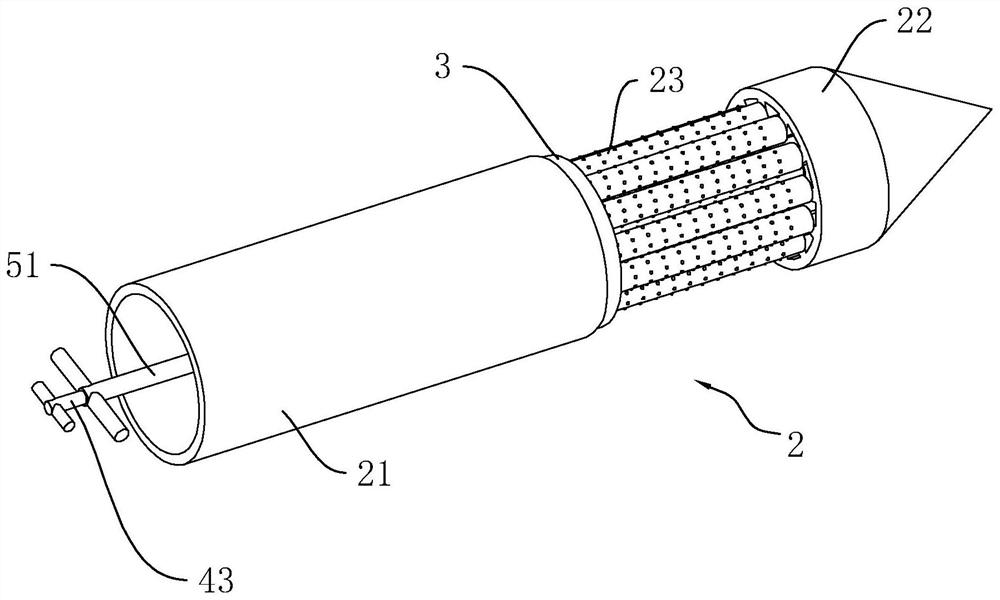
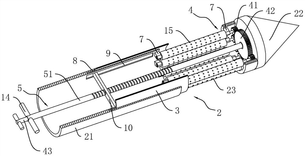
[0041] refer to figure 1 and figure 2 The drain pipe 2 includes an extension cylinder 21 , an insertion cylinder 22 and a rotating roller 23 rotatably connected between the extension cylinder 21 and the insertion cylinder 22 . Both the extension cylinder 21 and the insertion cylinder 22 are hollow inside, and the extension cylinder 21 is fixedly connected to one side of the support plate 1 . The rotating roller 23 is rotatably connected to the end of the extension cylinder 21 away from the support plate 1, and the end of the rotating rol...

Embodiment 2

[0050] This embodiment discloses a construction method of a foundation pit support structure.

[0051] A construction method for a foundation pit support structure, comprising the following steps:

[0052] S1. Measure and set out the line and excavate the soil layer to form a foundation pit;

[0053] S2. Determine the location where drainage is required, and use a drilling machine to drill holes on the side wall of the foundation pit. The diameter of the drilled holes is slightly smaller than the outer diameter of the drain pipe 2, and then install the support plate 1. During the installation of the support plate 1 , inserting the drainage pipe 2 into the corresponding drill hole, so that the support plate 1 is tightly attached to the side wall of the foundation pit;

[0054] S3. Open drainage holes on the support plate 1, drain the water in the support plate 1 into the corresponding drainage ditch, and use a water pump to pump the water away.


PUM


Abstract

The present application relates to a foundation pit support structure and a construction method thereof, comprising a support plate, wherein the support plate is an internal hollow structure, a drain pipe is provided on one side of the support plate, and the drain pipe includes an extension cylinder , a plug-in cylinder and a rotating roller connected between the extension cylinder and the plug-in cylinder, the extension cylinder is connected to the support plate, the rotating roller is rotatably connected to the end of the extension cylinder away from the support plate, the rotating roller The end away from the extension cylinder is rotatably connected to the end face of the plug-in cylinder, the axis direction of the rotating roller is parallel to the axis direction of the extension cylinder, and a gap is left between the adjacent rotating rollers to form a drainage space, and the extension cylinder slides on the The drain pipe is connected with a cover cylinder and is provided with a drive assembly for driving all the rotating rollers to rotate at the same time. The drain pipe is provided with a pusher for driving the cover cylinder to slide. The side of the support plate facing away from the drain pipe corresponds to the drain pipe. The position of the device is provided with an operation port that can be opened and closed. The present application has the effect of facilitating the removal of clogged soil.

Description

technical field [0001] The present application relates to the field of building construction, in particular to a foundation pit support structure and a construction method thereof. Background technique [0002] The foundation pit is an earth pit excavated at the foundation design position according to the base level and foundation plane size. The foundation pit excavated on some foundations will be lower than the groundwater level, and the groundwater will seep into the foundation pit, which will easily affect the stability of the side wall of the foundation pit. [0003] The Chinese invention patent with the existing notification number CN107794931B discloses a foundation pit support structure, including a support plate with a cavity, and a support pipe is installed on the side of the support plate, and the support pipe can be inserted into the side of the foundation pit In the wall soil, the water in the soil can enter the support pipe and flow into the inner cavity of th...

Claims


Application Information

Patent Timeline
Patent Type & Authority Patents(China)
IPC IPC(8): E02D17/04E02D19/10E02D19/06
CPCE02D17/04E02D19/10E02D19/06
Inventor 叶玉明林尧陈谏张弘辉郑光鸿
Owner 福建中骏长鑫建工有限公司
Features
  • R&D
  • Intellectual Property
  • Life Sciences
  • Materials
  • Tech Scout
  • Unparalleled Data Quality
  • Higher Quality Content
  • 60% Fewer Hallucinations
Learn More