Gas trapping device for space suction type electric propulsion system

A gas-capturing and air-breathing technology, applied in thrust reversers, using plasma, machines/engines, etc., can solve problems such as low air capture efficiency and hinder air capture efficiency, and reduce the probability of reverse motion , Improve the effect of storage performance

Pending Publication Date: 2021-06-29
INST OF MECHANICS - CHINESE ACAD OF SCI
View PDF0 Cites 0 Cited by
  • Summary
  • Abstract
  • Description
  • Claims
  • Application Information

AI Technical Summary

Problems solved by technology

[0006] The purpose of the present invention is to provide a gas capture device for a space-breathing electric propulsion system to solve the problem of low air capture efficiency in the prior art, and air particles collide with the capture pipe in the gas capture device and rebound Create technical issues that hinder air capture efficiency

Method used


Image

  • Gas trapping device for space suction type electric propulsion system
  • Gas trapping device for space suction type electric propulsion system
  • Gas trapping device for space suction type electric propulsion system

Examples


Embodiment 1

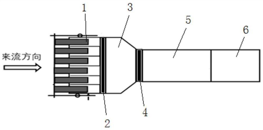
[0039] like figure 1 As shown, the present invention provides a gas capture device for a space-breathing electric propulsion system, the gas captured by the gas capture device is decelerated and pressurized by a pressurized storage device 5, and is driven by an electric thruster 6 spacecraft Proper thrust is provided during flight, and the gas trapping device includes a collimator main body 1 and a gas trapping device main body 3 in sequence along the gas flow direction. The collimator main body 1 is installed at the gas inlet end of the main body 3 of the gas trapping device.

[0040] The collimator main body 1 is a hollow tubular telescopic assembly, the pipe of the collimator main body 1 is parallel to the flow direction of air molecules, and the collimator main body 1 forms a plurality of narrow and adjustable length gas traps Flow channel to increase the gas capture rate.

[0041]Specifically, the collimator main body 1 has a hollow cylindrical structure with openings a...

Embodiment 2

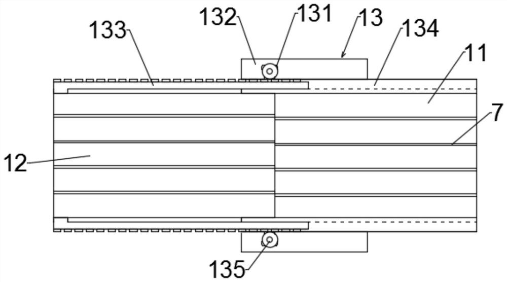
[0065] This embodiment provides an embodiment of the collimator body 1 corresponding to Embodiment 1, as image 3 As shown, each of the collimator main bodies 1 includes a fixed part 11, a telescopic part 12 and a driving part 13, and the fixed part 11 is used for fixed connection with the first molecular pump, wherein the first molecular pump is installed on Between the fixed part 11 and the parallel section 31 of the main body 3 of the gas trapping device; axial sliding; the drive part 13 is used to drive the telescopic part 12 to expand and contract along the axial direction of the fixed part 11 during space flight to adjust the length of the collimator main body 1, and the first spacer The plate 7 is disposed inside the fixed part 11 , and the telescopic part 12 is driven by the driving part 13 to completely shrink and overlap the fixed part 11 .

[0066] The collimator body 1 is located at the front end of the parallel section 31 of the gas capture device body 3 , and the ...


PUM


Abstract

The invention discloses a gas trapping device for a space suction type electric propulsion system. The gas trapping device sequentially comprises a collimator body and a gas trapping device body in the gas flowing direction. The collimator body is a hollow tubular telescopic assembly, a pipeline of the collimator body is parallel to the flowing direction of air molecules, and the collimator body forms a long and narrow gas trapping flow channel to improve the gas trapping efficiency. A first directional guiding assembly for guiding gas molecules into the gas trapping device body in a directional flowing manner is arranged between the collimator body and the gas trapping device body. A second directional guide assembly for enabling the gas molecules to enter a pressurizing storage device in a directional flowing manner is arranged between the gas trapping device body and the pressurizing storage device. According to the gas trapping device for the space suction type electric propulsion system, the target gas trapping efficiency is obtained by adjusting the length of the collimator body, through two stages of gas directional guide pumps, the forward motion probability of air particles in the gas trapping device body is increased, and the air trapping efficiency is improved.

Description

technical field [0001] The invention relates to the technical field of air-breathing electric propulsion spacecraft, in particular to a gas capture device for a space air-breathing electric propulsion system. Background technique [0002] Air-breathing electric propulsion is a very potential propulsion technology for long-term orbit maintenance of ultra-low orbit spacecraft. This technology does not need to carry propellant from the ground, but captures gas molecules in the thin atmosphere of space, decelerates and pressurizes them and provides them as propellant to the electric thruster. The air-breathing electric propulsion system mainly includes a gas capture device, a pressurized storage device, and an electric thruster. The gas capture device is located at the front end of the air-breathing electric propulsion system. The storage devices are connected. [0003] In order to efficiently capture gas molecules, the air-breathing electric propulsion system needs to use a g...

Claims


Application Information

Patent Timeline
Patent Type & Authority Applications(China)
IPC IPC(8): F03H1/00
CPCF03H1/0087
Inventor 杨超孙泉华黄河激刘洪伟肖雅彬
Owner INST OF MECHANICS - CHINESE ACAD OF SCI
Why Eureka
Try Eureka