
Ceiling fan capable of not hurting people when falling from high place

A high-altitude, ceiling fan technology, applied in the components, electromechanical devices, electrical components, etc. of the pumping device used for elastic fluid, can solve the problems of life safety hazards, loose ceiling, ceiling fan falling, etc., to ensure life and health, The effect of protecting life safety and simple structure

Inactive Publication Date: 2021-06-29
钟长侣
View PDF0 Cites 0 Cited by
  • Summary
  • Abstract
  • Description
  • Claims
  • Application Information

AI Technical Summary

Problems solved by technology

[0004] When the ceiling fan is in use, it will vibrate. When the ceiling fan is used for a long time, it will shake periodically after a long period of vibration, and the fixed structure on the ceiling will become loose. The ceiling fan will fall from the top due to insufficient fastening force, and the blades of the falling ceiling fan are still rotating. great harm

Method used


Image

  • Ceiling fan capable of not hurting people when falling from high place
  • Ceiling fan capable of not hurting people when falling from high place
  • Ceiling fan capable of not hurting people when falling from high place

Examples


Embodiment 1

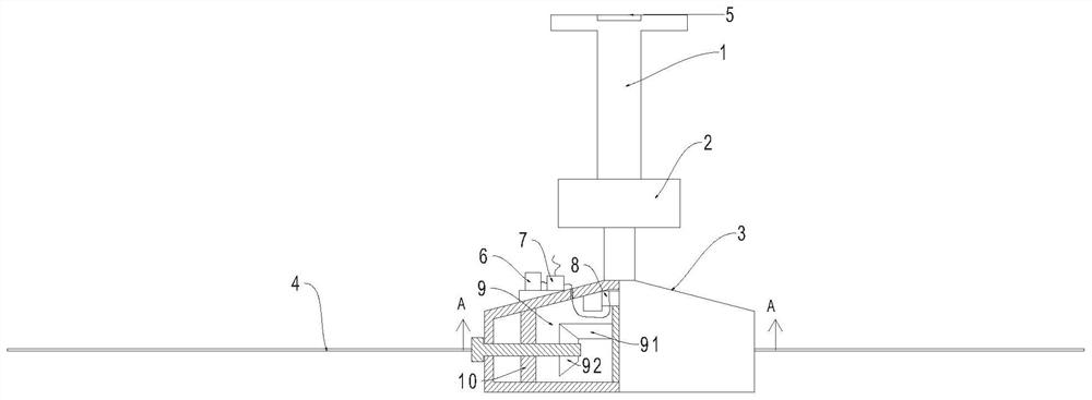
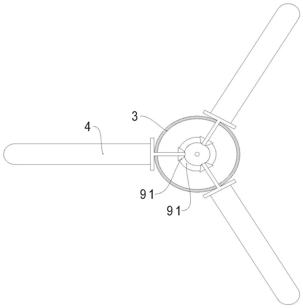
[0024] Example 1: See figure 1 - A ceiling fan that will not hurt people if dropped from a height, it includes a boom 1, a control box 2, a fan head 3 and at least one fan blade 4, the fan blades 4 are evenly distributed in the circumferential direction of the fan head 3, and the boom 1. The upper end is fixed on the part to be installed (ceiling) through a fixed structure (generally screws and bolts, etc.). The lower end of the boom 1 is connected to the upper end of the control box 2. The lower end of the control box 2 is provided with a rotating shaft, which is far away from the control box 2. One end is connected with the upper end of the fan head 3, and the control box 2 is the prior art, and the outside of the control box 2 is connected to the power supply, and the control box 2 controls the rotation of the rotating shaft.

[0025] The upper end of the boom 1 is provided with a groove, and a pressure sensor 5 is arranged in the groove. After the boom 1 is fixed, the pres...

Embodiment 2

[0033] Embodiment 2: Different from Embodiment 1, a rubber pad is arranged in the groove at the upper end of the suspender 1, and the rubber pad is located between the pressure sensor 5 and the inner bottom wall of the groove. The elasticity of the rubber pad makes the pressure sensor reduced pressure damage.

Embodiment 3

[0034] Embodiment 3: Different from Embodiment 2, the edge of the fan blade 4 is covered with a rubber sleeve, which makes the edge of the fan blade 4 sharp and becomes an elastic part, further ensuring the safety of the blower personnel.


PUM


Abstract

The invention relates to the technical field of fans, and discloses a ceiling fan capable of not hurting people when falling from a high place. The ceiling fan comprises a suspender, a control box, a fan head and at least one fan blade, the upper end of the suspender is fixed on a to-be-mounted part, the lower end of the suspender is connected with the upper end of the control box, the lower end of the control box is provided with a rotating shaft, one end of the rotating shaft away from the control box is connected with the upper end of the fan head, the control box controls the rotating shaft to rotate, a groove is formed in the upper end of the suspender, a pressure sensor is arranged in the groove, a battery and a controller are arranged on the outer side wall of the fan head, the controller is electrically connected with the battery through a first wire, a cavity is formed inside the fan head, a motor and a rotating structure are arranged in the cavity, the motor is electrically connected with the controller through a second wire, the pressure sensor is electrically connected with the controller through a third wire, after the fan blades are installed, the fan blades are in the horizontal direction, the motor drives a rotating structure to rotate, the fan blades are made to rotate to the vertical direction, and the life safety of air blowing personnel is guaranteed.

Description

technical field [0001] The invention relates to the technical field of fans, in particular to a ceiling fan that will not hurt people if dropped from a high place. Background technique [0002] Fan refers to an electric fan used to generate wind for cooling in hot weather. It is a device driven by electricity to generate airflow. [0003] The ceiling fan is a kind of fan, and the ceiling fan is generally fixed on the ceiling, so it is called a ceiling fan. Cools off the heat very well. [0004] When the ceiling fan is in use, it will vibrate. When the ceiling fan is used for a long time, it will shake periodically after a long period of vibration, and the fixed structure on the ceiling will become loose. The ceiling fan will fall from the top due to insufficient fastening force, and the blades of the falling ceiling fan are still rotating. Great harm. Contents of the invention [0005] The invention provides a ceiling fan which cannot hurt people when dropped from a hi...

Claims


Application Information

Patent Timeline
Patent Type & Authority Applications(China)
IPC IPC(8): F04D25/08F04D29/34F04D27/00H02K7/116H02K7/14
CPCF04D25/088F04D27/008F04D29/34H02K7/1163H02K7/14
Inventor 钟长侣
Owner 钟长侣
Learn More