Piezoelectric ultrasonic detection probe section for oil pipeline and detector in pipeline

A technology for oil pipelines and internal detectors, which is applied in the analysis of solids using sonic/ultrasonic/infrasonic waves, material analysis using sonic/ultrasonic/infrasonic waves, and pipes/pipe joints/pipe fittings, etc. Increase the length of the probe section, etc., to achieve the effect of improving stability and reliability, reducing volume and length, and simple structure

Pending Publication Date: 2021-06-29
苏州普莱瑞检测科技有限公司
View PDF2 Cites 0 Cited by
  • Summary
  • Abstract
  • Description
  • Claims
  • Application Information

AI Technical Summary

Problems solved by technology

The structure of these probe sections is combined with a single-chip ultrasonic probe as a unit, which will cause several problems: firstly, the number of probes required is too large, and each probe has a wire, resulting in messy probe section wires and a complicated structure. Not only equipment installation The debugging is complicated, and the failure rate of equipment will also increase greatly; too many second probes will increase the length of the probe section, which will firstly affect the passability, and secondly, put forward higher requirements for the length of the receiving and receiving bulb
However, due to the oblique incidence of the probes during real-time crack detection, if the probes are still gathered in such a small space, the sound fields between the probes will interfere with each other
At the same time, the total number of probes combined with conventional ultrasonic probes using a single chip is limited, so that the resolution of the detector is limited

Method used


Image

  • Piezoelectric ultrasonic detection probe section for oil pipeline and detector in pipeline
  • Piezoelectric ultrasonic detection probe section for oil pipeline and detector in pipeline
  • Piezoelectric ultrasonic detection probe section for oil pipeline and detector in pipeline

Examples


Embodiment Construction

[0046]In order to make the object, technical solution and advantages of the present invention clearer, the present invention will be described in further detail below in conjunction with specific embodiments and with reference to the accompanying drawings.

[0047] It should be noted that, unless otherwise defined, the technical terms or scientific terms used in the embodiments of the present invention shall have the usual meanings understood by those skilled in the art to which the present disclosure belongs. "First", "second" and similar words used in the present disclosure do not indicate any order, quantity or importance, but are only used to distinguish different components. "Comprising" or "comprising" and similar words mean that the elements or items appearing before the word include the elements or items listed after the word and their equivalents, without excluding other elements or items. Words such as "connected" or "connected" are not limited to physical or mechani...


PUM


Abstract

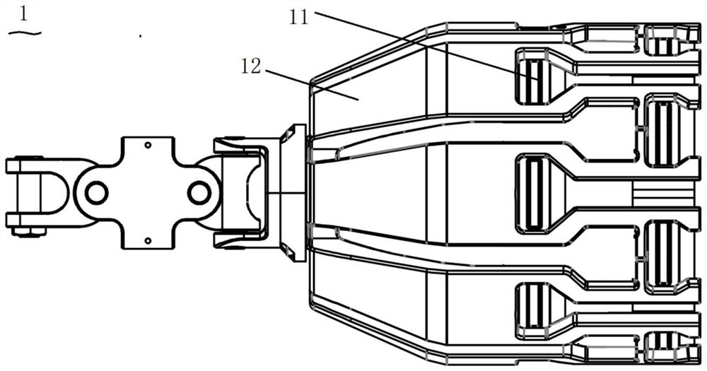
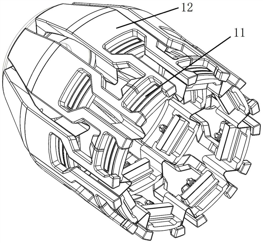
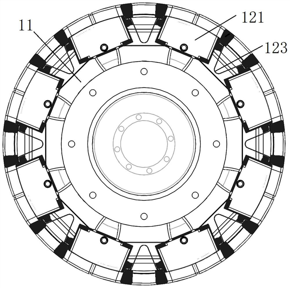
The invention provides a piezoelectric ultrasonic detection probe section for an oil pipeline and a detector in the pipeline, and relates to the technical field of nondestructive testing. The piezoelectric ultrasonic detection probe section comprises at least two rows of array type probes, each row of array type probes comprises at least two ultrasonic detection array type probes which are uniformly distributed in the circumferential direction of the pipeline in an array mode, each ultrasonic detection array type probe covers a certain circumferential detection area, and the circumferential detection areas covered by all the array type probes are combined together to complete the detection full coverage of the pipe wall in the circumferential direction. The ultrasonic detection array type probes are combined by a plurality of wafers, the formed ultrasonic detection array probe is connected with an electronic cabin through a multi-core cable, the size and the length of the probe section are greatly reduced, and the number of channels of the detector is possibly increased. The probe and the detector are simple in structure, and the stability and the reliability of the probe tightly attached to the pipe wall are improved.

Description

technical field [0001] The invention relates to the technical field of non-destructive testing, in particular to a piezoelectric ultrasonic detection probe section and an in-pipeline detector for oil pipelines. Background technique [0002] Long-distance pipelines have become an important means of transportation for transporting energy such as oil and natural gas. During the operation of the oil and gas pipeline, the surrounding geographical environment of the pipeline will cause corrosion to the pipe wall. When the corrosion reaches a certain stage, the pipeline will cause stress corrosion in the corrosion area under the action of external and internal pressure of the pipeline, resulting in cracks. When the crack on the pipe wall If it expands to a certain extent, it will cause leakage, posing a threat to national property and life safety around the pipeline. In order to ensure the safe operation of long-distance pipelines, regular inspections must be carried out in order ...

Claims


Application Information

Patent Timeline
IPC IPC(8): F16L55/38G01N29/04G01N29/24G01N29/265G01N17/00F16L101/30
CPCF16L55/38F16L2101/30G01N17/00G01N29/04G01N29/048G01N29/2437G01N29/265G01N2291/023G01N2291/0289G01N2291/0421G01N2291/0422
Inventor 李剑侯耀民钱国钟
Owner 苏州普莱瑞检测科技有限公司
Why Eureka
Try Eureka