Hydraulic pipe-jacking grouting machine

A grouting machine and hydraulic technology, applied in roads, constructions, road repairs, etc., can solve the problems of destructive road conditions, high operating costs, and affecting normal traffic, etc., and achieve simple and convenient operation, low manufacturing cost, length and The effect of size reduction

Active Publication Date: 2016-07-06
瑞森新建筑有限公司
View PDF8 Cites 2 Cited by
  • Summary
  • Abstract
  • Description
  • Claims
  • Application Information

AI Technical Summary

Problems solved by technology

However, drilling holes from top to bottom on the pavement is too destructive to the pavement, and it directly affects the normal traffic during the construction process. In addition, the existing equipment for penetrating the grouting pipe into the roadbed has complex structures and high operating costs. The disadvantages of high cost and low efficiency of pipe penetration

Method used


Image

  • Hydraulic pipe-jacking grouting machine
  • Hydraulic pipe-jacking grouting machine
  • Hydraulic pipe-jacking grouting machine

Examples


Embodiment Construction

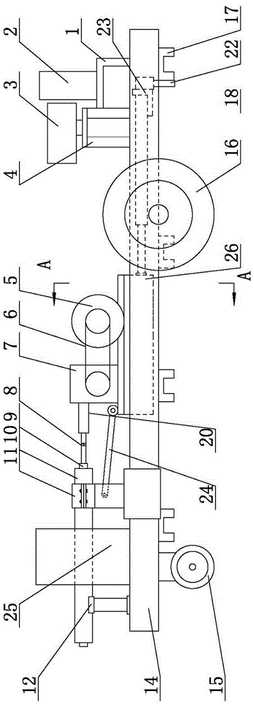
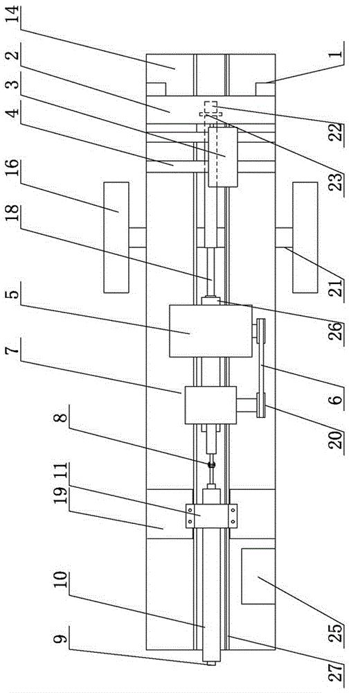
[0009] Stress testing platform of the present invention, such as figure 1 with figure 2 As shown, the frame 14 is included, and a guide rail 27 is respectively provided on both sides of the frame 14 along its length direction, and the guide rail 27 and the frame 14 can be made into one body. The hydraulic station 2 is installed at the rear of the frame 14, and the pipe card sliding seat 19, the motor sliding seat 26 and the hydraulic cylinder sliding seat 23 are installed successively on the frame 14 from front to back. Pipe card sliding seat 19, motor sliding seat 26 and hydraulic cylinder sliding seat 23 can slide along guide rail 27 respectively. To reduce sliding friction, such as Figure 7 As shown, the parts on both sides of the frame 14 can be made of channel steel, the channel steel is the guide rail 27, and the opening of the channel steel forms a guide groove inwardly, and the pipe clamp slide seat 19, the motor slide seat 26 and the hydraulic cylinder slide seat ...


PUM


Abstract

A hydraulic pipe-jacking grouting machine comprises a machine frame, wherein a guide rail is arranged on the two sides of the machine frame in the length direction of the machine frame respectively, a hydraulic station is installed at the rear portion of the machine frame, a pipe clamp sliding seat, a motor sliding seat and a hydraulic cylinder sliding seat are sequentially installed on the machine frame from front to back and can respectively slide along the guide rails, a first hydraulic cylinder is horizontally installed on the hydraulic cylinder sliding seat, a second hydraulic cylinder is vertically installed on the hydraulic cylinder sliding seat, the first hydraulic cylinder and the second hydraulic cylinder are communicated with the hydraulic station through grouting pipes, the second hydraulic cylinder is located behind the first hydraulic cylinder, a piston rod of the first hydraulic cylinder is connected with the motor sliding seat, and a motor driving mechanism is installed on the motor sliding seat.The hydraulic pipe-jacking grouting machine has the advantages that the hydraulic pipe-jacking grouting machine is designed to be of a horizontal perforated pipe-penetrating structure, a hydraulic system is adopted for providing pipe-penetrating power for the grouting pipes, then the grouting pipes can horizontally penetrate into a roadbed by being matched with a drilling mechanism, and a guarantee is provided for follow-up grouting work.The drilling process can be slow and powerful through hydraulic control, and operation is simple and convenient.

Description

technical field [0001] The invention belongs to the field of high-pressure grouting equipment, in particular to a hydraulic pipe jacking grouting machine. Background technique [0002] After long-term use of expressways, the road surface will partially subside. At present, the commonly used repair method is: first drive the grouting pipe vertically downward from the road surface into the subgrade, and then use a high-pressure grouting machine to inject the easily solidified substance or mixture (water, cement slurry, water glass, etc.) into the rock formation or Accurate injections are made in the cracks and cavities of the soil to achieve the purpose of reducing water seepage and consolidating rock formations and soil. However, drilling holes from top to bottom on the pavement is too destructive to the pavement, and it directly affects the normal traffic during the construction process. In addition, the existing equipment for penetrating the grouting pipe into the roadbed ...

Claims


Application Information

Patent Timeline
IPC IPC(8): E01C23/10
CPCE01C23/10
Inventor 高守峰高明芹
Owner 瑞森新建筑有限公司
Why Eureka
Try Eureka