
Manufacturing method of heat exchange device

A manufacturing method and heat exchange device technology, applied in the direction of heat exchanger types, indirect heat exchangers, refrigerators, etc., to achieve good heat exchange effect and large surface area

Inactive Publication Date: 2021-06-29
金竟(广州)科技有限责任公司
View PDF11 Cites 1 Cited by
  • Summary
  • Abstract
  • Description
  • Claims
  • Application Information

AI Technical Summary

Problems solved by technology

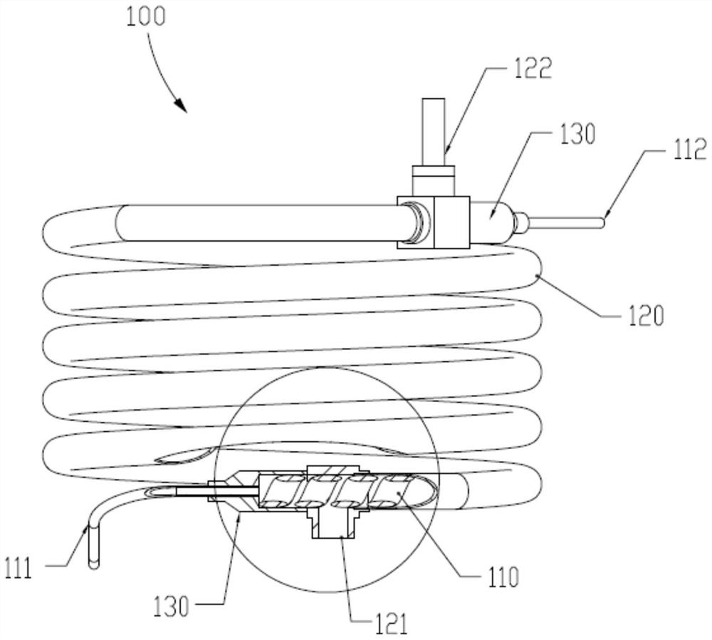
3He dense phase liquid flows in the heat exchange section of the J-T tube, so the requirement for the heat exchange section of the J-T tube is that the required cross-sectional area of ​​the inner tube in the radial direction of the outer tube should be smaller, so as to control the outer tube. The flow rate of the reflux working medium in the tube, but at the same time, the surface area of ​​the inner tube is required to be as large as possible to improve the heat transfer efficiency. There is no good solution to this contradiction in the prior art.

Method used


Image

  • Manufacturing method of heat exchange device
  • Manufacturing method of heat exchange device
  • Manufacturing method of heat exchange device

Examples


Embodiment Construction

[0034] The present invention will be further described in detail below in conjunction with the accompanying drawings and embodiments. It should be understood that the specific embodiments described here are only used to explain the present invention, but not to limit the present invention. In addition, it should be noted that, for the convenience of description, only some structures related to the present invention are shown in the drawings but not all structures.

[0035] In the description of the present invention, unless otherwise clearly specified and limited, the terms "connected", "connected" and "fixed" should be understood in a broad sense, for example, it can be a fixed connection, a detachable connection, or an integrated ; It can be directly connected or indirectly connected through an intermediary. Those of ordinary skill in the art can understand the specific meanings of the above terms in the present invention according to specific situations.

[0036] The tech...


PUM


Abstract

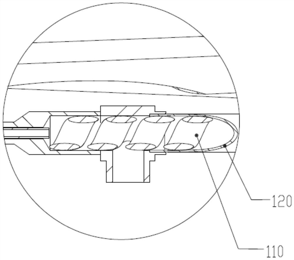
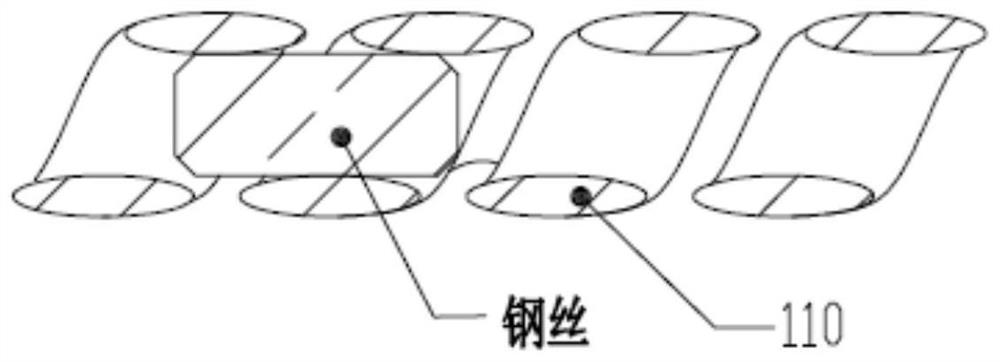
The invention discloses a manufacturing method of a heat exchange device. The manufacturing method comprises the following steps that A, an inner pipe is flattened; B, the inner pipe is wound into a spiral shape; C, the spiral inner pipe is placed into an outer pipe to form a pipe set; and D, the pipe set is wound into a spiral shape to form the heat exchange device. The heat exchange device manufactured through the manufacturing method of the heat exchange device is good in heat exchange effect, the working medium of 0.7-0.8K from a distillation chamber can be reduced to 0.05K or below, and the heat exchange requirement is completely met.

Description

technical field [0001] The invention relates to the technical field of heat exchange, in particular to a method for manufacturing a heat exchange device. Background technique [0002] In the scientific and technological fields such as quantum superconducting computing, quantum transport, quantum materials and superconducting magnets, dilution refrigerators and related low-temperature equipment and instruments are usually used. At this stage, more and more ultra-low temperature equipment use non-liquid helium refrigeration. Form, which is known as the dry refrigeration method in the industry. However, since the cold source of dry refrigeration can only provide a temperature range of about 4.0K, it is necessary to further reduce the refrigeration temperature. For example, a dilution refrigerator needs to be able to reach a temperature below 3 He liquefaction in order to work normally. This requires a further step. The cooling device, so as to further reduce the temperature of...

Claims


Application Information

Patent Timeline
Patent Type & Authority Applications(China)
IPC IPC(8): F28D7/14F25B9/02
CPCF28D7/14F25B9/02F25B9/002
Inventor 潘娟段娜
Owner 金竟(广州)科技有限责任公司
Learn More