

Equipment and method for managing user load abnormity at special transformer metering point
A technology for managing users and metering points. It is applied in the direction of measuring electrical variables, measuring devices, and instruments. It can solve problems such as installation environment requirements, management work requirements, and difficulty in construction organization, so as to improve the reliability of power lines, Achieve failure prevention management and shorten inspection time
- Summary
- Abstract
- Description
- Claims
- Application Information
AI Technical Summary
Problems solved by technology
Method used
Image

Examples
Embodiment Construction
[0040]In order to better understand the technical content of the present invention, specific embodiments are given together with the attached drawings for description as follows. Aspects of the invention are described in this disclosure with reference to the accompanying drawings, which show a number of illustrated embodiments. Embodiments of the present disclosure are not necessarily intended to include all aspects of the invention. It should be appreciated that the various concepts and embodiments described above, as well as those described in more detail below, can be implemented in any of numerous ways, since the concepts and embodiments disclosed herein are not limited to any implementation. In addition, some aspects of the present disclosure may be used alone or in any suitable combination with other aspects of the present disclosure.
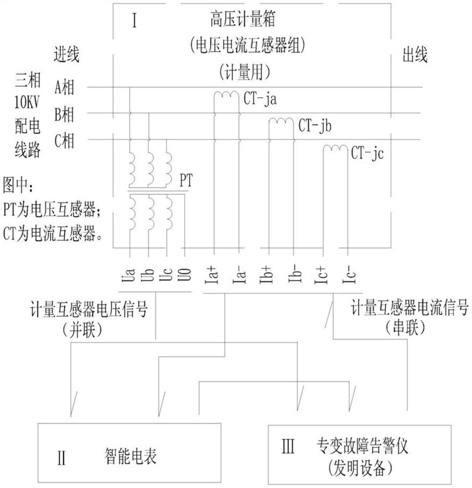
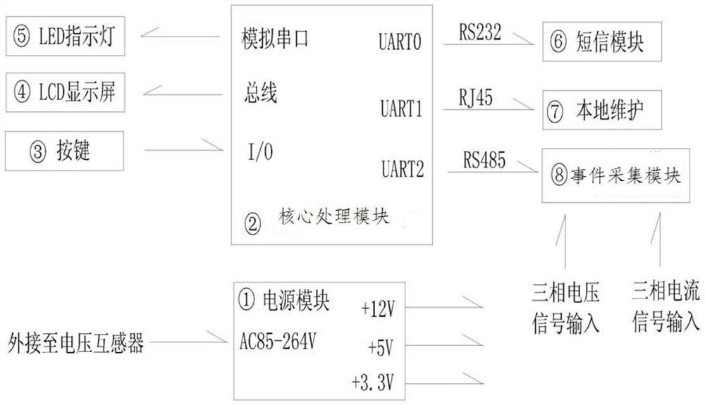
[0041] Such as Figure 1-2 As shown in Fig. 1, a special variable metering point manages the abnormal user load equipment, including ...
PUM
 Abstract
Description
Claims
Application Information