
Unmanned aerial vehicle inspection method, device and equipment for wind power blade detection

A technology for wind turbine blades and drones, applied in non-electric variable control, three-dimensional position/course control, vehicle position/route/height control, etc., can solve drone damage, affect load and stiffness matrix, and reduce blade life and operational safety to reduce the risk of impact, improve inspection efficiency, and save planning time

Active Publication Date: 2021-06-29
XIAMEN UNIV OF TECH
View PDF15 Cites 3 Cited by
  • Summary
  • Abstract
  • Description
  • Claims
  • Application Information

AI Technical Summary

Problems solved by technology

Due to the complex operating environment of the wind farm, the wind turbine blades operate at high altitude around the clock, and are affected by various factors such as wind and sand, pollution, lightning strikes and typhoons for a long time. The wind turbine blades are prone to defects and gradually expand. If the defects of the wind turbine blades are not found in time, it will be Directly affects the load and stiffness matrix, ultimately reducing blade life and operational safety
[0003] At present, the inspection of the fan blades is controlled by manual operation during the flight process of the UAV. It is easy to hit the fan and cause damage to the UAV and increase the damage to the surface of the fan blade. Moreover, due to the limitation of personnel operation technology, the fan cannot be inspected. The blades are photographed in all directions, resulting in missing shots and reducing the accuracy of inspections

Method used


Image

  • Unmanned aerial vehicle inspection method, device and equipment for wind power blade detection
  • Unmanned aerial vehicle inspection method, device and equipment for wind power blade detection
  • Unmanned aerial vehicle inspection method, device and equipment for wind power blade detection

Examples


Embodiment Construction

[0040] In order to make the objects, technical solutions, and advantages of the present invention more clearly, the technical solutions in the embodiments of the present invention will be described in contemplation in the drawings of the embodiments of the present invention, and the embodiments described in the embodiments of the present invention will become apparent. It is a part of the embodiments of the invention, not all of the embodiments. Based on the embodiments in the present invention, those of ordinary skill in the art will belong to the scope of the present invention without all other embodiments obtained without creative labor. Thus, the following detailed description of the embodiments of the invention as provided in the drawings are not intended to limit the scope of the invention as claimed, but only the selected embodiments of the present invention are shown. Based on the embodiments in the present invention, those of ordinary skill in the art will belong to the s...


PUM


Abstract

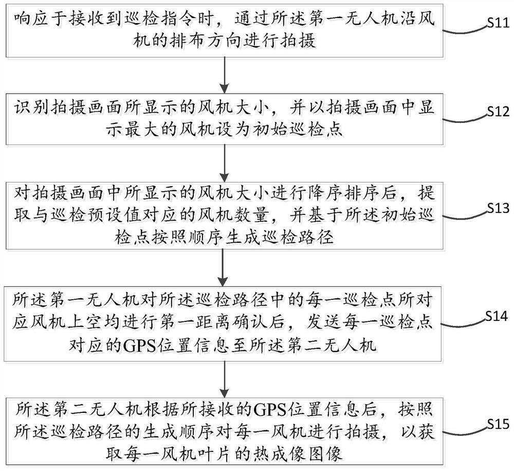
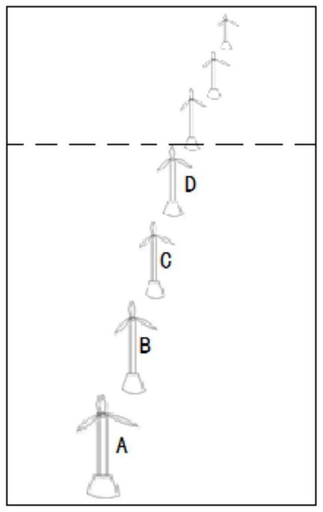
The invention discloses an unmanned aerial vehicle inspection method for wind power blade detection, and the method is realized based on an unmanned aerial vehicle system, and the method comprises the steps: carrying out the photographing through a first unmanned aerial vehicle in the arrangement direction of a fan in response to a received inspection instruction; identifying the size of the fan displayed in the shot picture, and setting the fan with the largest display in the shot picture as an initial inspection point; after the sizes of the fans displayed in the shot picture are sorted in a descending order, extracting the number of the fans corresponding to an inspection preset value, and generating inspection paths according to the sequence based on the initial inspection points; enabling the first unmanned aerial vehicle to send GPS position information corresponding to each inspection point to the second unmanned aerial vehicle after confirming a first distance above a fan corresponding to each inspection point in the inspection path; and enabling the second unmanned aerial vehicle to shoot each fan according to the generation sequence of the routing inspection path according to the received GPS position information so as to obtain a thermal imaging image of each fan blade.

Description

Technical field [0001] The present invention relates to the field of wind turbines, and more particularly to a drone patrol method and apparatus and apparatus for wind-moving blades detection. Background technique [0002] Wind energy is an important renewable energy. With the expansion of my country's wind energy market, the wind turbine manufacturing gradually entered a rapid development period. The life and safety of wind turbines affect wind power utilization and development, fan blades are core components of wind turbines, their life and safety directly affect the life and security of the entire wind turbine. Since the wind farm operates more complicated, the wind turbine blade is running all-weather in high-altitude, long-term receiving wind, pollution, lightning strikes, and typhoon, the fan blade is prone to defects and gradually expands. If it is not possible to find the fan blade defect, will It directly affects the load and stiffness matrix, which ultimately reducing t...

Claims


Application Information

Patent Timeline
Patent Type & Authority Applications(China)
IPC IPC(8): G05D1/10
CPCG05D1/101
Inventor 周伟杰张旻澍刘文豪
Owner XIAMEN UNIV OF TECH
Learn More