Medical infusion tube smashing treatment device

A processing device and infusion tube technology, applied in grain processing, magnetic separation, solid separation, etc., can solve the problems of poor control effect, inability to realize automatic cutting, inability to realize automatic crushing, etc., and achieve the effect of beating

Pending Publication Date: 2021-07-02
赖仕萌
View PDF8 Cites 2 Cited by
  • Summary
  • Abstract
  • Description
  • Claims
  • Application Information

AI Technical Summary

Problems solved by technology

[0005] In order to overcome the shortcomings of traditional infusion tube crushing devices, such as poor control effect, inability to realize automatic cutting and automatic crushing, the technical problem of the present invention is to provide a medical infusion tube crushing device with good control effect, automatic cutting and automatic crushing processing device

Method used


Image

  • Medical infusion tube smashing treatment device
  • Medical infusion tube smashing treatment device
  • Medical infusion tube smashing treatment device

Examples


Embodiment 1

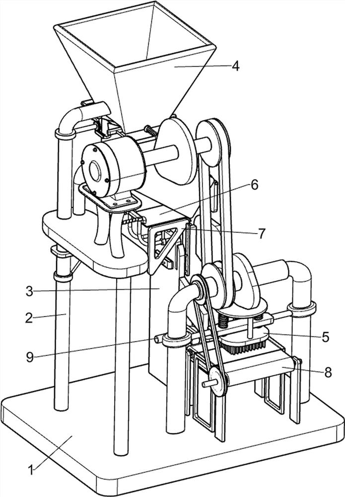
[0071] Medical infusion tube pulverization treatment device, such as figure 1As shown, including the bottom plate 1, the first support frame 2, the conductive frame 3, the cutting assembly 4, and the pulverizing assembly 5, and the bottom plate 1 is provided with a first support frame 2, and the bottom plate 1 is provided on the back right portion. Fixing frame 3, the upper portion of the first support frame 2 is provided with a cutting assembly 4, and a pulverizing assembly 5 is provided on the front side of the bottom plate 1.

[0072] When people want to pulverize the infusion tube, this medical infusion tube pulverization treatment apparatus can be used. First, the user starts the cutting assembly 4, and the cutting assembly 4 can be operated by the pulverizing assembly 5, and then put the infusion tube into the cutting assembly. In the cutting assembly 4, the disconnecting assembly 4 is cut off, and the cut-off infusion tube falls from the cutting assembly 4 on the conductive...

Embodiment 2

[0074] On the basis of Example 1, such as figure 2 with image 3 As shown, the cutting assembly 4 includes a speed reduction motor 41, a first rotating shaft 42, a first cam 43, a hopper 44, a U-shaped connecting rod 45, a telescopic rod 46, a first tool 47, a second axis 48, a gear 49, and a rack. 410, the upper front side of the upper portion of the first support frame 2 has a reduction motor 41, and the reduction motor 41 output shaft is connected to the first rotating shaft 42, and the first spindle 42 is provided with a first cam 43, and the upper portion of the first support frame 2 is provided. The bucket 44, the front and rear sides of the hopper 44 are provided with a telescopic rod 46, and there is a U-shaped connecting rod 45 on both telescopic rods 46, and both U-shaped connecting rods 45 are provided with a first tool 47, and the first support. The upper rear side rotation type of the frame 2 is provided with a second axis 48, and a gear 49 is provided on the second ro...

Embodiment 3

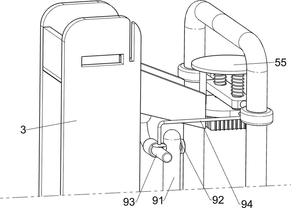
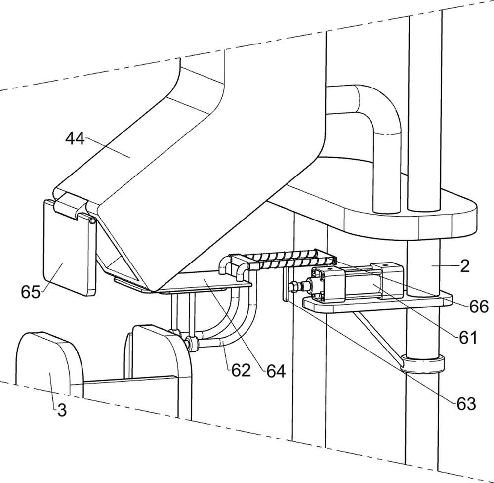
[0079] On the basis of Example 2, such as Figure 4 - Figure 7 As shown, there is an intermittent lower material assembly 6, and the first support frame 2 and the conductive frame 3 are provided with a batch lower material assembly 6, and the intermittent lower material assembly 6 includes a cylinder 61, a third support frame 62, a shaped connection. The rod 63, the breakboard plate 64, the baffle 65, and the second spring 66, the lower portion of the first support frame 2 mounts the cylinder 61, and the upper left side of the conductive frame 3 is provided with a third support frame 62, the third support frame 62. The upper sliding is provided with a breakboard plate 64, and there is two second spring 66 on the ferrule plate 64, and the second spring 66 is connected to the third support frame 62 and the breakboard 64, respectively, the cylinder 61 telescopic rod and the break A shaped connecting rod 63 is connected between the plate 64, and the lower rotation of the hopper 44 is p...


PUM


Abstract

The invention relates to a smashing treatment device, in particular to a medical infusion tube smashing treatment device. The medical infusion tube smashing treatment device is good in control effect and capable of achieving automatic cutting-off and automatic smashing. The medical infusion tube smashing treatment device comprises a bottom plate, a guide frame, a cutting assembly and a cutting assembly, wherein a first supporting frame is arranged on the left side of the bottom plate, the guide frame is arranged at the right part of the rear side of the bottom plate, the cutting assembly is arranged on the upper portion of the first supporting frame, and the smashing assembly is arranged on the right portion of the front side of the bottom plate. According to the medical infusion tube smashing treatment device, a second cam is in contact fit with a tool rest, so that the tool rest is driven to move downwards, then a second tool is driven to move downwards, a first spring is compressed, the second tool crushes an infusion tube on a workbench, and the crushing effect is achieved.

Description

Technical field [0001] The present invention relates to a pulverization treatment apparatus, and more particularly to a medical infusion tube pulverization treatment device. Background technique [0002] Traditional medical infusion tube pulverizer, when used for a long time, it is not possible to have better ventilation heat, and the device protection effect is poor. It is easy to damage. When the device is operating normally, the infusion tube is difficult to control, and operation It is not possible that the alarm signal cannot be conveyed in time. [0003] Patent Application CN208131644U, Publication No. 20181123, discloses a medical infusion tube pulverizing device, including a device body, a support column, a feed tank, a pulverizing machine, an electric chassis, a rotating shaft, a connecting chassis, and a pulverizing device, etc. By putting the infusion tube into the feed tank, the infusion tube falls into the pulverizing machine feed tank, and then falls from the pulver...

Claims


Application Information

Patent Timeline
Patent Type & Authority Applications(China)
IPC IPC(8): B09B3/00B02C19/00B03C1/26B03C1/30
CPCB09B3/0075B02C19/0075B03C1/26B03C1/30B02C2201/06
Inventor 赖仕萌
Owner 赖仕萌
Why Eureka
Try Eureka