Scara robot joint disturbance compensation method

A technology for robot joints and disturbance compensation, applied in manipulators, program-controlled manipulators, manufacturing tools, etc., can solve problems affecting the accuracy of disturbance compensation, affect the speed of disturbance compensation, and the difficulty of friction modeling, so as to enhance the robustness of the system , Improve the control accuracy and improve the effect of adaptability

Pending Publication Date: 2021-07-02
ROKAE SHANDONG INTELLIGENT TECH CO LTD
View PDF6 Cites 0 Cited by
  • Summary
  • Abstract
  • Description
  • Claims
  • Application Information

AI Technical Summary

Problems solved by technology

The high tempo of the 3C industry requires scara to be controlled more stably, faster, and more accurately. At present, the first joint and the second joint of scara mostly use a motor plus harmonic deceleration structure, which introduces disturbances such as joint flexibility and friction, which reduces the robot’s performance. control accuracy
[0004] 1) In the robot controller, the disturbance compensation is realized through algorithms such as the observer, and the convergence time of the observer is long, which affects the rapidity of disturbance compensation
[0005] 2) It is difficult to model the friction force of the main disturbance item, and it is difficult to obtain accurate friction force, which affects the accuracy of disturbance compensation
[0006] 3) The load of the robot changes in real time, and the constant gain disturbance compensation is not learning

Method used


Image

  • Scara robot joint disturbance compensation method
  • Scara robot joint disturbance compensation method
  • Scara robot joint disturbance compensation method

Examples


Embodiment Construction

[0027] Embodiments of the present invention are described in detail below, examples of which are shown in the drawings, wherein the same or similar reference numerals designate the same or similar elements or elements having the same or similar functions throughout. The embodiments described below by referring to the figures are exemplary and are intended to explain the present invention and should not be construed as limiting the present invention.

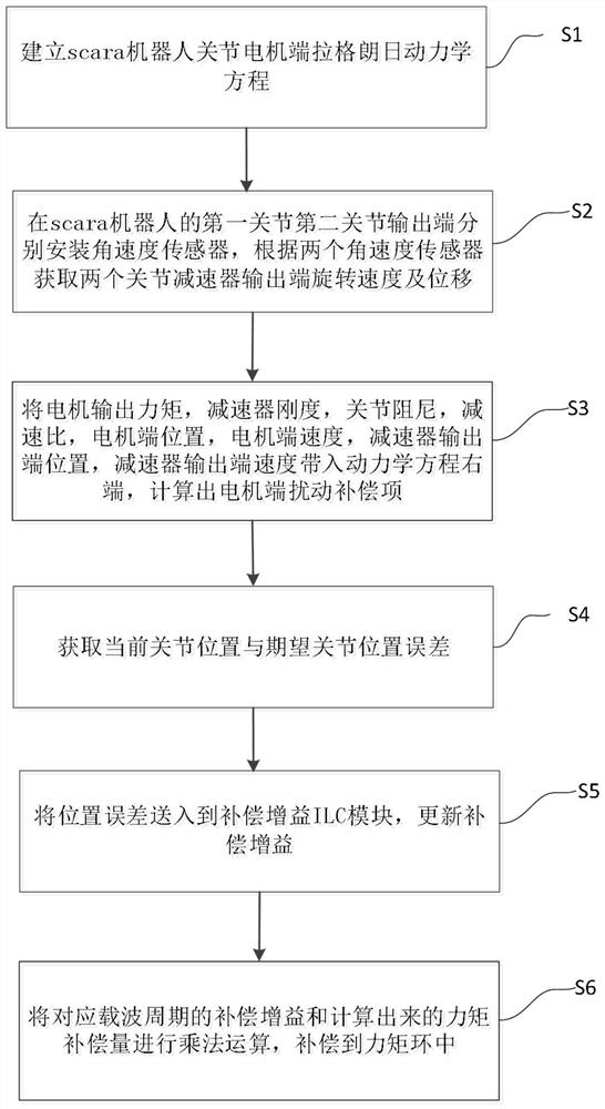
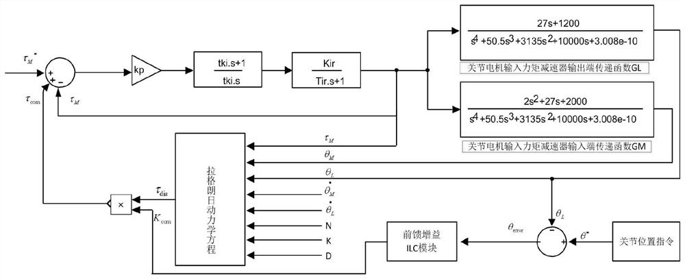
[0028] like figure 1 and figure 2 As shown, the scara robot joint disturbance compensation method of the embodiment of the present invention includes the following steps:

[0029] Step S1, establishing the Lagrangian dynamic equation of the scara robot joint motor end,

[0030]

[0031] Among them, M m is the motor inertia; is the motor end acceleration; D m is the coefficient of sliding friction at the motor end; is the motor end speed; f m is the Coulomb friction coefficient at the motor end; τ m is the torque app...


PUM


Abstract

The invention provides a scara robot joint disturbance compensation method. The method comprises the steps that a scara robot joint motor end lagrangian dynamics equation is established; angular velocity sensors are installed at the output ends of a first joint and a second joint of a scara robot respectively, and the rotating speed and displacement of the output ends of two joint speed reducers are obtained according to the two angular velocity sensors; a motor end disturbance compensation item is calculated; the error between the current joint position and the expected joint position is obtained; the position error is sent to a compensation gain ILC module, and compensation gain is updated; and multiplication is conducted on the compensation gain corresponding to a carrier cycle and the calculated torque compensation amount, and the compensation gain is compensated into a torque ring. According to the method, the disturbance compensation amount is calculated through a kinetic model; the disturbance compensation effect is further optimized by multiplying the compensation amount by the variable compensation gain; the compensation gain is optimized through ILC iterative learning, and the learning adaptive capacity is achieved for load changes.

Description

technical field [0001] The invention relates to the technical field of industrial robots, in particular to a joint disturbance compensation method of a scara robot. Background technique [0002] In recent years, with the gradual improvement of industrial automation, the application fields of industrial robots have continued to develop from automobiles, electronic appliances, machinery and other industries to other application fields, and have become an indispensable part of many industrial occasions. Among them, scara robots are used in 3C industry has been widely used. The high tempo of the 3C industry requires scara control to be more stable, faster, and more accurate. At present, the first joint and the second joint of scara mostly use a motor plus harmonic deceleration structure, which introduces disturbances such as joint flexibility and friction, which reduces the robot’s performance. control precision. [0003] Although some control methods can solve these problems ...

Claims


Application Information

Patent Timeline
IPC IPC(8): B25J9/16B25J9/04
CPCB25J9/1651B25J9/042
Inventor 韩峰涛庹华刘超丛曹华张航韩建欢雷鸿于文进钱鹏
Owner ROKAE SHANDONG INTELLIGENT TECH CO LTD
Why Eureka
Try Eureka