
Cement blending device for hydraulic engineering construction

A water conservancy project and cement technology, which is applied in water conservancy projects, water conservancy engineering equipment, cement mixing devices, etc., can solve problems such as low mixing effect, inability to fully mix cement, and low mixing efficiency, so as to achieve improved mixing effect, stable structure, and improved Effect of Stirring Efficiency

Inactive Publication Date: 2021-07-02
SHANDONG PROVINCE WATER CONSERVANCY BUREAU CO LTD
View PDF7 Cites 2 Cited by
  • Summary
  • Abstract
  • Description
  • Claims
  • Application Information

AI Technical Summary

Problems solved by technology

Water is an indispensable precious resource for human production and life, but its natural state does not fully meet human needs. Only by building water conservancy projects can water flow be controlled, floods prevented, and water volume adjusted and distributed to meet the needs of human beings. People's living and production needs for water resources. Water conservancy projects need to build different types of hydraulic structures such as dams, dikes, spillways, sluices, water inlets, channels, crossings, rafts, fishways, etc., to achieve their goals. A large amount of cement is needed in the construction process of the project. Manual mixing of cement requires a lot of manual labor, and the cement cannot be fully mixed. The mixing effect is low, and the mixing efficiency is low. Therefore, we propose a cement for hydraulic engineering construction deployment device

Method used


Image

  • Cement blending device for hydraulic engineering construction
  • Cement blending device for hydraulic engineering construction
  • Cement blending device for hydraulic engineering construction

Examples


Embodiment Construction

[0021] The following will clearly and completely describe the technical solutions in the embodiments of the present invention with reference to the accompanying drawings in the embodiments of the present invention. Obviously, the described embodiments are only some, not all, embodiments of the present invention. Based on the embodiments of the present invention, all other embodiments obtained by persons of ordinary skill in the art without making creative efforts belong to the protection scope of the present invention.

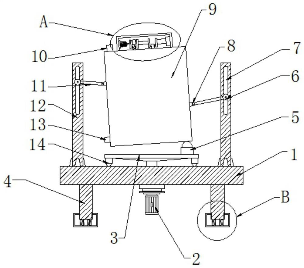
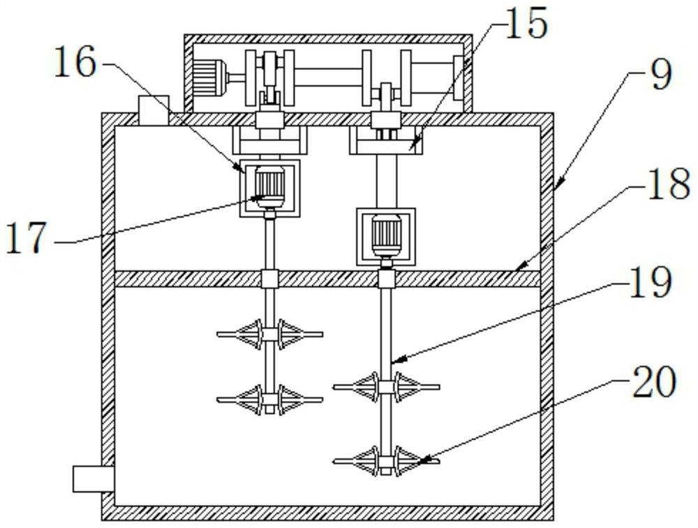
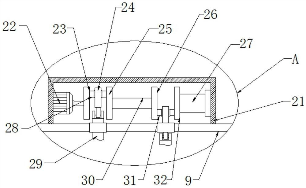
[0022] see figure 1 , the present invention provides a technical solution: a cement blending device for water conservancy construction, including a mounting plate 1, the four corners of the lower end surface of the mounting plate 1 are fixedly connected with supporting legs 4, and the lower end surfaces of the supporting legs 4 are provided with shock absorbers. The center of the lower end surface of the mounting plate 1 is provided with a driving motor 2, the...


PUM


Abstract

The invention discloses a cement blending device for hydraulic engineering construction. The cement blending device for hydraulic engineering construction comprises a mounting plate; supporting legs are fixedly connected to the four corners of the lower end face of the mounting plate correspondingly; damping devices are arranged on the lower end faces of the supporting legs correspondingly; a driving motor is arranged at the center of the lower end face of the mounting plate; the upper end of a motor shaft of the driving motor penetrates through the mounting plate to the upper portion of the mounting plate; a rotating disc is fixedly connected to the upper end face of the motor shaft of the driving motor; supporting balls are evenly arranged on the outer ring of the lower end face of the rotating disc; supporting plates are arranged on the left side and the right side of the upper end face of the mounting plate; strip-shaped open holes are formed in the upper portions of the front end faces of the supporting plates; sliding seats are movably connected in inner cavities of the strip-shaped open holes; movable rods are movably connected in inner cavities of the sliding seats; and the other ends of the movable rods are movably connected with connecting seats. The device is simple in structure and convenient to operate, and the stirring efficiency and the stirring effect are effectively improved.

Description

technical field [0001] The invention relates to the technical field of hydraulic engineering, in particular to a cement blending device for hydraulic engineering construction. Background technique [0002] Water conservancy projects are projects built to control and allocate natural surface water and groundwater to achieve the purpose of eliminating harm and rejuvenating profits, also known as water projects. Water is an indispensable precious resource for human production and life, but its natural state does not fully meet human needs. Only by building water conservancy projects can water flow be controlled, floods prevented, and water volume adjusted and distributed to meet the needs of human beings. People's living and production needs for water resources. Water conservancy projects need to build different types of hydraulic structures such as dams, dikes, spillways, sluices, water inlets, channels, crossings, rafts, fishways, etc., to achieve their goals. A large amount...

Claims


Application Information

Patent Timeline
Patent Type & Authority Applications(China)
IPC IPC(8): B28C5/18F16F15/067E02B1/00
CPCB28C5/18B28C5/0806B28C5/0831B28C5/0856F16F15/067E02B1/00
Inventor 张峰田茂志牛之庚
Owner SHANDONG PROVINCE WATER CONSERVANCY BUREAU CO LTD
Learn More