
Distributed buoyancy configuration subsurface buoy system with section real-time power supply and communication functions

A communication function, distributed technology, applied in the field of submersible system, can solve the problems of increased risk of rope breakage, waste of resources, loss of instrument packages, etc., to improve continuous power supply time, improve work stability, and avoid bending and knotting Effect

Active Publication Date: 2021-07-02
TONGJI UNIV
View PDF15 Cites 5 Cited by
  • Summary
  • Abstract
  • Description
  • Claims
  • Application Information

AI Technical Summary

Problems solved by technology

[0003] However, with the deepening of marine research, traditional submersible buoys are difficult to meet the needs. For example, in the research of deep blue oceans, it is often necessary to measure data between different layers, so it is necessary to configure multiple instrument packages. Strength rope connection, but because the marine environment is very complex, the actual power consumption of different sensors changes dynamically, it is difficult to match the capacitance of each sensor according to the actual power consumption during design, which leads to the realization of the same work The duration requires a battery with a larger capacity, which causes a waste of resources. In addition, due to the complex environment in the deep blue ocean, the risk of rope breakage increases. After the rope breaks, it is easy to cause the loss of the instrument bag.

Method used


Image

  • Distributed buoyancy configuration subsurface buoy system with section real-time power supply and communication functions
  • Distributed buoyancy configuration subsurface buoy system with section real-time power supply and communication functions
  • Distributed buoyancy configuration subsurface buoy system with section real-time power supply and communication functions

Examples


Embodiment Construction

[0029] The present invention will be described in detail below with reference to the accompanying drawings and specific examples. The present embodiment is implemented in terms of the technical solution of the present invention, and a detailed embodiment and a specific operation process are given, but the scope of the invention is not limited to the following examples.

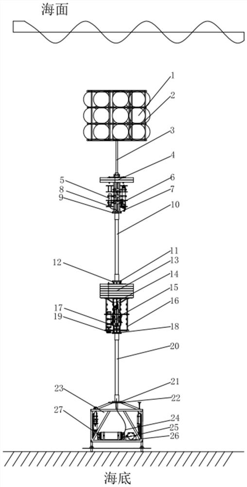
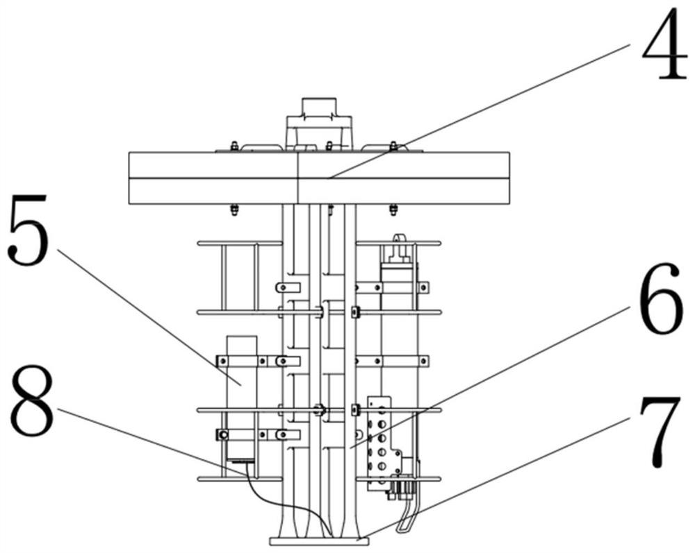
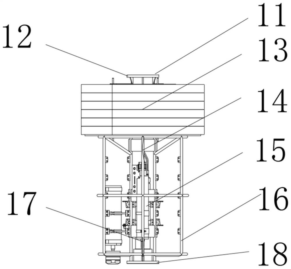
[0030] A distributed buoyancy configuration sub-assembly built-in buoyancy with a profile real-time power supply and communication function, such as Figure 1 to 4 As shown, including the floating ball group 1, the dash device, and a plurality of instrument packs provided between the floating ball group 1 and the ducting device, characterized in that there is between adjacent instruments and instruments and instruments and Between the insertion device, the floating ball group 1 and the instrument package are connected between the tie rope, and the underwater power supply 26 is provided, and the sensor in each instr...


PUM


Abstract

The invention relates to a distributed buoyancy configuration subsurface buoy system with section real-time power supply and communication functions, which comprises a floating ball group, a sinking device and a plurality of instrument bags which are sequentially connected in series and arranged between the floating ball group and the sinking device, the adjacent instrument bags are connected through an electric force bearing cable, and the instrument bags and the sinking device are connected through an electric force bearing cable. The floating ball set is connected with the instrument bags through mooring ropes, an underwater power source is arranged in the sinking device, the sensors in the instrument bags are connected to the underwater power source through electrical force bearing cables, and distributed buoyancy pieces are further arranged in the instrument bags. Compared with the prior art, real-time power supply and large-data-volume communication of instruments at all observation layers of the section of the subsurface buoy system are realized through the electrical bearing cable; the underwater power supply is arranged in the sinking device and serves as a concentrated power supply, the continuous power supply time of the submerged buoy under the same capacitance is prolonged, and the power supply serves as an auxiliary weight to help sinking. In addition, the distributed buoyancy pieces are arranged on the instrument bag, so that the situation that the instrument bag is lost due to breakage of the mooring cable connected with the instrument bag is avoided.

Description

Technical field [0001] The present invention relates to an abnormal system suitable for deep blue oceans, in particular, involving a distributed buoyancy configuration sub-assembly system having a cross-sectional real-time power supply and communication function. Background technique [0002] For a long time, my country's sub-observation technology is relatively tradition, multi-use steel cable, nylon rope, etc., which is placed on a particular layer in a particular layer according to the research demand, usually in different layers after the sub-recovery. Bit data acquisition. [0003] However, with the in-depth of ocean research, the traditional subcompachment is difficult to meet demand, such as deep blue ocean research, often need to measure data between different layers, so you need to configure multiple instrument packs, multiple instrument packs pass high Strength rope connection, but due to the very complex ocean environment, different sensor actual power consumption is d...

Claims


Application Information

Patent Timeline
Patent Type & Authority Applications(China)
IPC IPC(8): B63B22/00B63B22/04
CPCB63B22/00B63B22/04B63B2022/006
Inventor 金璐杨群慧吴正伟季福武周怀阳米智楠周伟
Owner TONGJI UNIV
Learn More