A light cavity floor, mold and processing technology

A cavity floor and processing technology, which is applied to molds, floors, auxiliary parts of molds, etc., can solve the problems of poor connectivity, difficult construction and production, and the influence of the overall structural strength of the cavity floor, so as to achieve structural integrity, improve pouring quality, The effect of improving processing quality

Active Publication Date: 2022-06-07
ZHEJIANG FANHUA ENG SUPERVISION
View PDF5 Cites 0 Cited by
  • Summary
  • Abstract
  • Description
  • Claims
  • Application Information

AI Technical Summary

Problems solved by technology

[0004] In view of the above-mentioned related technologies, the inventor believes that the cavity floor adopts a layered structure, and the connection between the structures is poor, which affects the overall structural strength of the cavity floor and is not easy to construct.

Method used


Image

  • A light cavity floor, mold and processing technology
  • A light cavity floor, mold and processing technology
  • A light cavity floor, mold and processing technology

Examples


Embodiment 1

[0047] The embodiment of the present application discloses a lightweight cavity floor.

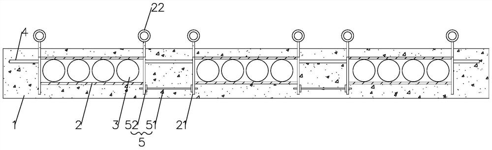
[0048] refer to figure 1 and 2 The cavity floor includes a concrete main board 1, a metal mesh cage 2 and a filling inner mold 3. The shape of the concrete main board 1 is shaped according to the design shape of the floor, and the thickness is also constructed according to the design size.

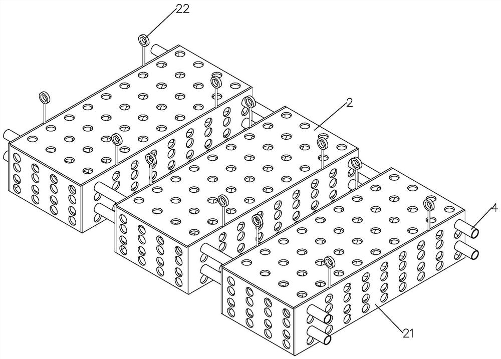
[0049] The metal mesh cage 2 is poured on the concrete main board 1 and is completely covered. The metal mesh cage 2 includes six metal mesh panels that surround a rectangular box. The metal mesh panels in this embodiment adopt a metal plate with a thickness of 4mm. A round hole with a diameter of 60mm is evenly cut out on the metal plate, and the metal mesh cage 2 is set as a flat box with relatively large upper and lower surfaces. The lower surface panel of the cage 2 is directly leaked on the lower surface of the concrete main board 1; the upper sides of the two side mesh panels 21 with larger len...

Embodiment 2

[0055] The embodiment of the present application discloses a mold for a lightweight cavity floor.

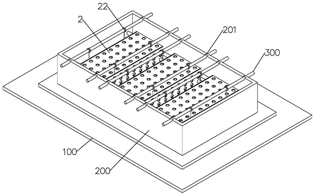
[0056] refer to figure 1 and 3 , the mold includes a bottom mold 100, a side mold 200 and a suspension main beam 300. The bottom form 100 is assembled and welded by steel plates, and the side forms 200 are fixed on the bottom form 100 and enclose the shape of the floor for pouring of the floor; the suspension main beam 300 is connected to the two opposite long sides of the side form 200 Between the plates, there are multiple groups of positioning grooves 201 with openings facing up on the two side plates opposite to the side formwork 200. The shape of the positioning grooves 201 is U-shaped. In the positioning groove 201, the suspension main beam 300 can be prevented from moving on the side formwork 200. In order to prevent the suspension main beam 300 from affecting the forming of the concrete main board 1, the height of the bottom of the positioning groove 201 is higher than...

Embodiment 3

[0059] The embodiment of the present application discloses a light cavity floor processing technology.

[0060] The processing technology includes the following steps:

[0061] S1, mold making, select the steel plate to cut and weld to form the bottom mold 100, select the steel plate and section steel to cut and weld to form the side mold 200, and install it on the bottom mold 100;

[0062] S2, the metal mesh cage 2 is made, and the metal mesh panels on the six sides of the metal mesh cage 2 are cut and fixed, and the metal suspension ring 22 is installed;

[0063] S3, the metal mesh cage 2 is put into the mold, the metal mesh cage 2 is suspended on the suspension main beam 300, and the suspension main beam 300 is placed on the side mold 200, and the metal mesh cage 2 is laid in the mold one by one;

[0064] S4, support structure installation, support the support bar 5 between adjacent metal mesh cages 2, and support the main beam 4 through a plurality of metal mesh cages 2 i...


PUM

PropertyMeasurementUnit
thicknessaaaaaaaaaa

Abstract

This application relates to the technical field of prefabricated buildings, in particular to a light cavity floor, mold and processing technology, including a concrete main board, a metal mesh cage set in the concrete main board, and a filling inner mold filled in the metal mesh cage; Several metal mesh cages are arranged along the length direction of the concrete main board, and the adjacent metal mesh cages are fixedly connected; the filling inner mold is evenly distributed in the metal mesh cage and fills the inner space of the metal mesh cage , the filling inner mold is provided with lightweight fillers. The cavity floor slab of the present application has the advantages of simple structure, high strength and simple construction steps, which greatly improves the processing efficiency of the cavity floor slab.

Description

technical field [0001] The application relates to the field of prefabricated buildings, in particular to a light-weight cavity floor, a mold and a processing technique. Background technique [0002] With the rapid development of my country's economic construction, concrete cavity slabs have been widely used in my country's construction projects. There are two main types of cavity slabs, one is cast-in-place concrete cavity slabs, and the other is prefabricated and cast-in-place concrete cavity slabs. The technical realization of the cast-in-place concrete cavity floor is mainly by filling the "inner mold" in the cast-in-place concrete. At present, the internal forms for filling cavity floors are all integral components, and these components can be hollow cores, boxes, or lightweight solid cylinders and blocks. However, their uses are the same, only as fillers, and their structures are the same, all of which are integral components. Although the concrete cavity slab techno...

Claims


Application Information

Patent Timeline
Patent Type & Authority Patents(China)
IPC IPC(8): E04B5/02E04C2/30E04C2/28B28B23/02B28B7/16B28B7/00
CPCE04B5/02E04C2/30E04C2/28B28B23/02B28B7/164B28B7/0002
Inventor 王成斌张智峰李胜姜泽文黄小芬
Owner ZHEJIANG FANHUA ENG SUPERVISION
Why Eureka
Try Eureka