
Transmission rod limiting airtight device special for aircraft high-lift system

A transmission rod and lift technology, which is applied in the direction of aircraft transmission, aircraft power device, aircraft power transmission, etc., can solve the problems of transmission rod movement, transmission rod passing through bearings, etc.

Active Publication Date: 2021-07-02
SHAANXI AIRCRAFT CORPORATION
View PDF6 Cites 2 Cited by
  • Summary
  • Abstract
  • Description
  • Claims
  • Application Information

AI Technical Summary

Problems solved by technology

[0003] The invention provides a transmission rod limiting airtight device for a high-lift system of an aircraft, which solves the movement and deformation of the transmission rod in the central wing section, and solves the sealing problem of the transmission rod passing through the airtight compartment and the non-airtight compartment and the lubrication of the bearing question

Method used


Image

  • Transmission rod limiting airtight device special for aircraft high-lift system
  • Transmission rod limiting airtight device special for aircraft high-lift system
  • Transmission rod limiting airtight device special for aircraft high-lift system

Examples


Embodiment Construction

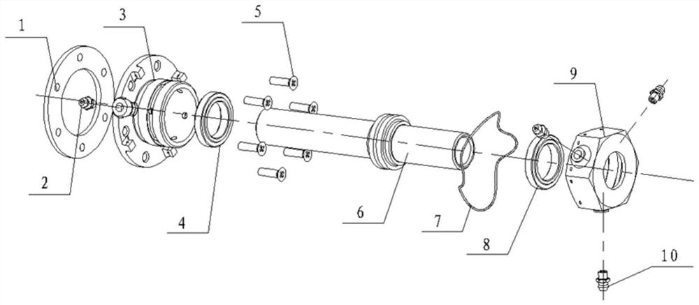
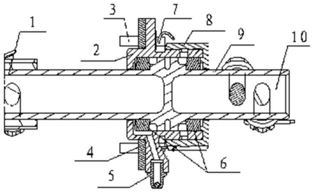
[0026] Such as figure 1 As shown, the airtight device for limiting the movement of the special transmission rod of the aircraft high-lift system includes: a flange 3, a rubber pad 1, a nut 9, a shaft 6, a screw 5, a grease nozzle 2, and a fuse 7. Bearings 4 are installed on both sides of the shaft, assembled between the flange 3 and the nut 9, the flange 3 and the nut 9 are installed with the oil nozzle 10, after assembly, the rubber pad 1 is placed, and it is fixed on the aircraft structure skin by screws , and finally put fuse 7 on flange plate 3 and nut 9.

[0027] Preferably, two lugs are designed in the middle of the shaft 6, and the clearance fit relationship between the lugs and the flange is in the form of a labyrinth seal.

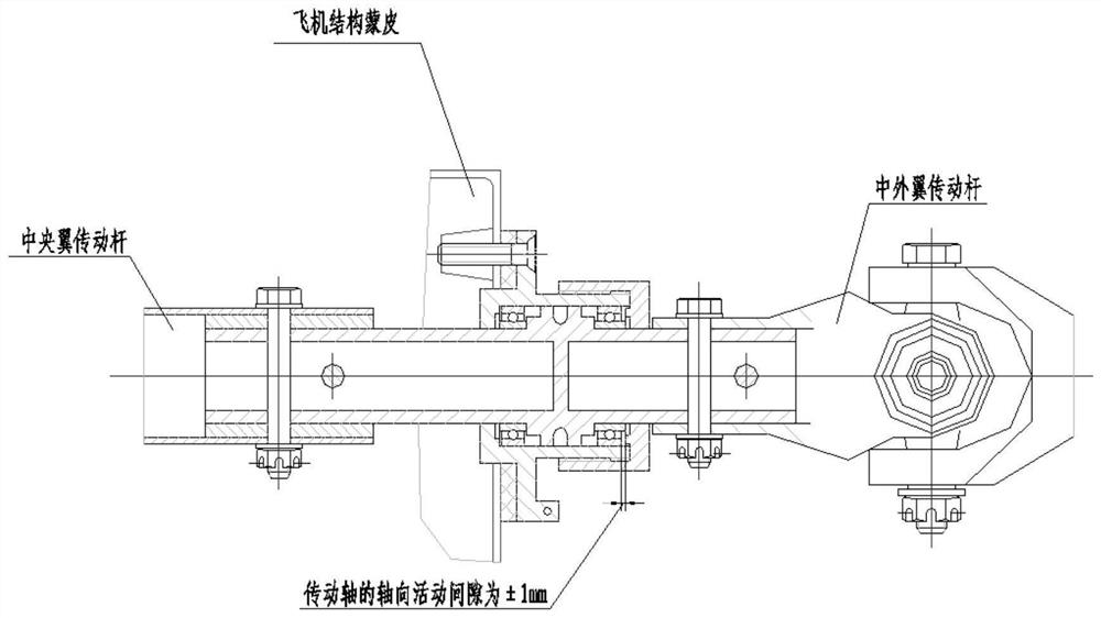
[0028] Preferably, after the shaft 6 and the bearing 4 are assembled between the flange and the nut, the shaft has a movement gap of ±1mm.

[0029] Preferably, when the flange plate 3 is assembled, the oil filling port should face the port cover...


PUM


Abstract

The invention belongs to the technical field of aviation sealing, and discloses a transmission rod limiting airtight device special for an aircraft high-lift system. The device is composed of a flange plate, rubber gaskets, a nut, a shaft, a bearing, an oil injection nozzle, screws, a bond strap and the like; and a stopper assembly is connected with the skin of a central wing structure through the screws and is leveled up through the rubber gaskets during connection, and a left wing and a right wing of a single machine are each provided with one piece. According to the device, transmission torque is transmitted from a central wing to a middle outer wing and transmitted from an airtight cabin to a non-airtight cabin, the device achieves movement limiting and airtight effects by arranging a movement gap, a labyrinth seal and the like, the maintainability is improved by arranging the oil injection nozzle, and the service life of the device is prolonged. The device is simple in structure and convenient to install and adjust, and the final assembly adjustment period of a high-lift control system is shortened.

Description

technical field [0001] The invention belongs to the technical field of aviation sealing, and particularly designs a special transmission rod limiting airtight device for high-lift systems of aircraft. Background technique [0002] The function of the aircraft high-lift control system is to increase the total lift of the wings and shorten the distance of take-off and landing roll. The main function of the high-lift control system is to transmit the torsional moment of the motor, and convert the rotational motion into reciprocating motion through the flap retraction mechanism to realize flap retraction. In order to realize the synchronous movement of the left and right flaps, the transmission rods of the left and right wings are connected and driven by the same motor. Therefore, the distribution of the flap transmission rods is from the central wing to the middle and outer wings. From an airtight cabin to a non-airtight cabin, the sealing technology of the transmission rod wi...

Claims


Application Information

Patent Timeline
Patent Type & Authority Applications(China)
IPC IPC(8): F16J15/16B64C13/30
CPCF16J15/16B64C13/30Y02T50/40
Inventor 程兴宏宋娟妮徐鸿洋崔津铭石强军杨涛车意彬何志国徐坚史振良
Owner SHAANXI AIRCRAFT CORPORATION
Learn More