

Timing circuit and timing method for measuring time difference between two paths of pulse signals
A technology of pulse signal and timing circuit, which is applied to devices for measuring time interval, pulse characteristic measurement, and electrical unknown time interval measurement, etc. , the effect of high measurement accuracy and simple hardware structure
- Summary
- Abstract
- Description
- Claims
- Application Information
AI Technical Summary
Problems solved by technology
Method used
Image

Examples
Embodiment 1
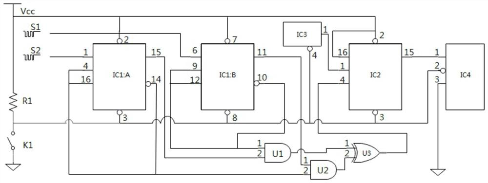
[0042] The specific embodiment 1 of the present invention discloses a timing circuit for measuring the time difference between two pulse signals, the circuit diagram is as follows figure 1 As shown, it includes: a first JK flip-flop, a second JK flip-flop, an AND gate U1, an AND gate 2, an OR gate U3 and a timing component; wherein, the CLK terminal of the first JK flip-flop receives one of the pulse signals, The J terminal, the K terminal and the Q non-terminal are connected to the second input terminal of the AND gate U2, and the Q terminal is connected to the second input terminal of the AND gate U1; the CLK terminal of the second JK flip-flop receives another pulse signal, and the J terminal, The K terminal and the Q non-terminal are connected to the first input terminal of the AND gate U1, and the Q terminal is connected to the first input terminal of the AND gate U2; the output terminal of the AND gate U1 is connected to the first input terminal of the OR gate U3 and the ...
Embodiment 2
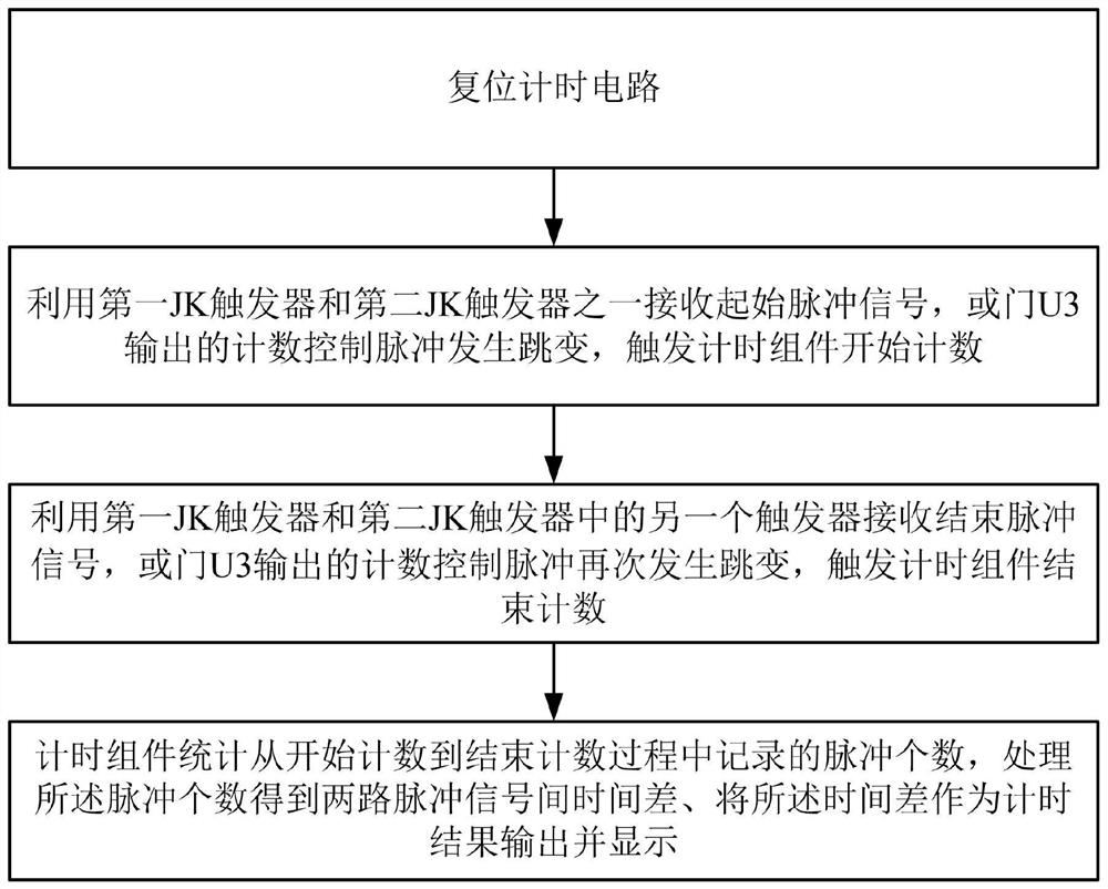
[0059] Embodiment 2 of the present invention discloses a timing method for measuring the time difference between two pulse signals, which is applicable to any timing circuit in Embodiment 1. Flowchart such as figure 2 As shown, the working method includes the following steps:
[0060] Step S1: reset the timing circuit;
[0061] Step S2: Use one of the first JK flip-flop and the second JK flip-flop to receive the start pulse signal, and the count control pulse output by the OR gate U3 jumps, triggering the timing component to start counting;
[0062] Step S3: use the other flip-flop of the first JK flip-flop and the second JK flip-flop to receive the end pulse signal, and the count control pulse output by the OR gate U3 jumps again, triggering the timing component to end counting;
[0063] Step S4: The timing component counts the number of pulses recorded from the start counting to the end counting process, processes the number of pulses to obtain the time difference between...
PUM
 Abstract
Description
Claims
Application Information