
Oil-immersed three-phase transformer

A three-phase transformer, oil-immersed technology, applied in the field of electric power, can solve the problems of high temperature of the transformer device, no fluidity of oil, and inability to dissipate and remove the heat of the transformer case in time.

Inactive Publication Date: 2021-07-02
山东迪米特电气有限公司
View PDF9 Cites 0 Cited by
  • Summary
  • Abstract
  • Description
  • Claims
  • Application Information

AI Technical Summary

Problems solved by technology

[0003] In the case of existing transformers immersed in oil, auxiliary cooling measures such as heat sinks are carried out on them. Since the oil inside the device has almost no fluidity, the heat in the transformer case cannot be dissipated and removed in time, and the temperature of the transformer device is too high. high

Method used


Image

  • Oil-immersed three-phase transformer
  • Oil-immersed three-phase transformer
  • Oil-immersed three-phase transformer

Examples


Embodiment 1

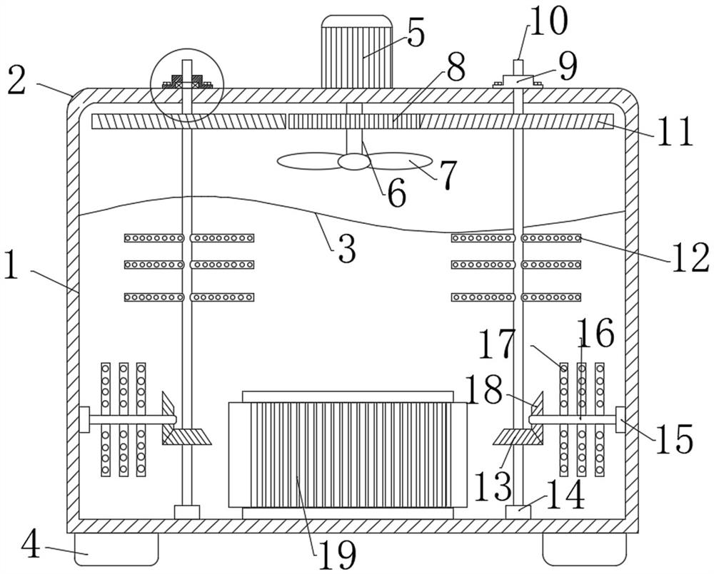
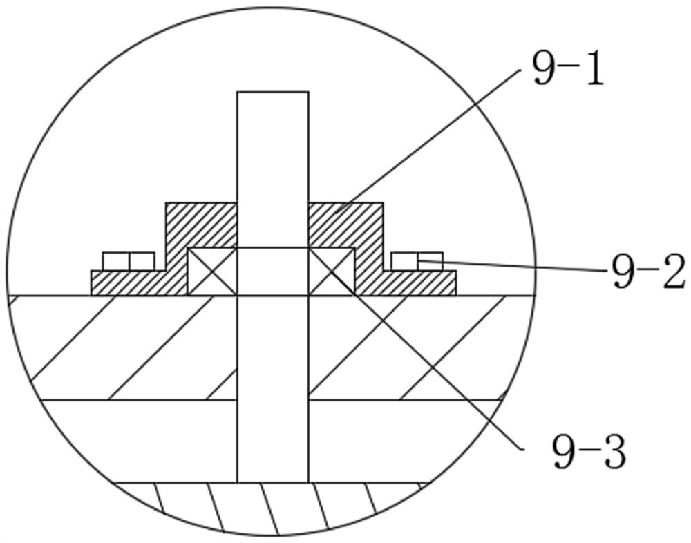
[0023] see Figure 1~3 , in the embodiment of the present invention, a kind of oil-immersed three-phase transformer comprises cabinet 1, and the effect of cabinet 1 is to receive the device inside; Motor 5 is installed on the top of cabinet 1, and motor 5 is the power unit of whole stirring device; Motor The output end of 5 is equipped with rotating shaft 6, and fan blade 7 is installed on the surface of rotating shaft 6, and the function of fan blade 7 is to cool down the part with higher temperature of the liquid surface on the top of engine oil; A bearing seat 9 is installed on the top side of the bearing seat 9, a second shaft 10 is installed inside the bearing seat 9, a second gear 11 is installed on the shoulder of the second shaft 10, and the gear 8 and the second gear 11 mesh with each other. Here The function of meshing is for transmission; the middle part of the second rotating shaft 10 is equipped with a stirring shaft 12, and the stirring shaft 12 is a device for s...

Embodiment 2

[0027] see figure 1 The difference between the embodiment of the present invention and embodiment 1 is that a third bearing seat 15 is installed on one side of the cabinet 1, a rotating rod 16 is installed in the middle of the third bearing seat 15, and a stirring rod is installed on the surface of the rotating rod 16 Device 17, the stirring rod device 17 is the same device as the above-mentioned stirring shaft 12, and its main function is to stir the part with poor fluidity at the bottom of the device; the side of the rotating rod 16 away from the third bearing seat 15 is equipped with a second The gear 18, the bevel gear 13, and the second bevel gear 18 mesh with each other, and the meshing of the bevel gears is also the effect of realizing the transmission.

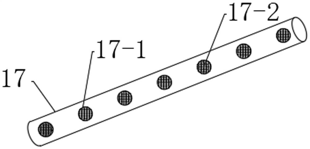
[0028] Stirring rod device 17 comprises the mesh 17-1 that offers on its surface, and the inside of mesh 17-1 is fixedly installed with mesh yarn 17-2, and mesh yarn 17-2 can increase the smooth flow effect of stirring...


PUM


Abstract

The invention discloses an oil-immersed three-phase transformer, relates to the field of electric power, and mainly aims to solve the cooling effect of a power transformer. The transformer comprises a case, a motor is mounted at the top of the case, a rotating shaft is mounted at the output end of the motor, fan blades are mounted on the surface of the rotating shaft, a gear is mounted in the middle of the rotating shaft, a bearing seat is mounted on the side edge of the top of the case, a second rotating shaft is mounted in the bearing seat, and a second gear is mounted on the shoulder of the second rotating shaft. The gear and the second gear are meshed with each other, and a stirring shaft is mounted in the middle of the second rotating shaft; a bevel gear is mounted at the bottom of the second rotating shaft; a second bearing seat is mounted between the bottom of the second rotating shaft and the case; a third bearing seat is mounted on one side of the case; a rotating rod is mounted in the middle of the third bearing seat, a stirring rod device is mounted on the surface of the rotating rod, a second bevel gear is installed on the side, away from the third bearing seat, of the rotating rod and meshed with the bevel gear. The bevel gear is meshed with the second bevel gear.

Description

technical field [0001] The invention relates to the field of electric power, in particular to an oil-immersed three-phase transformer. Background technique [0002] The distribution transformer is one of the important equipment in the power supply and distribution system of industrial and mining enterprises and civil buildings. It reduces the 10(6)kV or 35kV network voltage to the 230 / 400V bus voltage used by users. This type of product is suitable for AC 50 (60) Hz, three-phase maximum rated capacity of 2500kVA (single-phase maximum rated capacity of 833kVA, generally not recommended to use single-phase transformers), and can be used indoors (outdoors) when the capacity is 315kVA and below Can be installed on a pole, the ambient temperature is not higher than 40°C, not lower than -25°C, the highest daily average temperature is 30°C, the highest annual average temperature is 20°C, the relative humidity is not more than 90% (ambient temperature is 25°C), the altitude No more...

Claims


Application Information

Patent Timeline
Patent Type & Authority Applications(China)
IPC IPC(8): H01F27/14H01F27/08H01F27/06
CPCH01F27/14H01F27/085H01F27/06
Inventor 董晓东王金柱
Owner 山东迪米特电气有限公司
Learn More