Supercharge Your Innovation With Domain-Expert AI Agents!

Auxiliary correction device for gantry machining equipment

A technology for processing equipment and calibration devices, applied in metal processing equipment, positioning devices, measuring/indicating equipment, etc., can solve problems such as deformation deflection of machine tool guide rails, difficulty in determining the deformation cycle of gantry machine tool guide rails, and time-consuming clamping of workpieces, etc.

Inactive Publication Date: 2021-07-06
SHENZHEN CITY HUAQUN CNC MACHINERY
View PDF0 Cites 4 Cited by
  • Summary
  • Abstract
  • Description
  • Claims
  • Application Information

AI Technical Summary

Problems solved by technology

[0004] However, when testing the parallelism of the guide rails of the gantry machine tool according to the current usual method, it is difficult to determine the deformation cycle of the guide rails of the gantry machine tool. There will be no deflection during the continuous processing of batches of multiple workpieces, but if there is a deflection during the process, the parallelism of the workpiece clamping will be lacking. In addition, the parallelism has been measured before the processing starts, so The deformation and deflection of the guide rail of the machine tool during the entire continuous processing process is often ignored, which affects the processing accuracy. In addition, when the workpiece is clamped and positioned in the current gantry machining center, it is basically fixed separately and sequentially through multiple individual jacking blocks. On the worktable of the gantry machining center, the workpiece is clamped and positioned. Although the stable positioning and disassembly of the workpiece is realized, the separate disassembly and assembly of multiple individual top blocks makes the clamping of the workpiece extremely time-consuming and seriously affects the continuous Efficient production and processing use,

Method used


Image

  • Auxiliary correction device for gantry machining equipment
  • Auxiliary correction device for gantry machining equipment
  • Auxiliary correction device for gantry machining equipment

Examples


Embodiment Construction

[0025] The following will clearly and completely describe the technical solutions in the embodiments of the present invention with reference to the accompanying drawings in the embodiments of the present invention. Obviously, the described embodiments are only some, not all, embodiments of the present invention. Based on the embodiments of the present invention, all other embodiments obtained by persons of ordinary skill in the art without making creative efforts belong to the protection scope of the present invention.

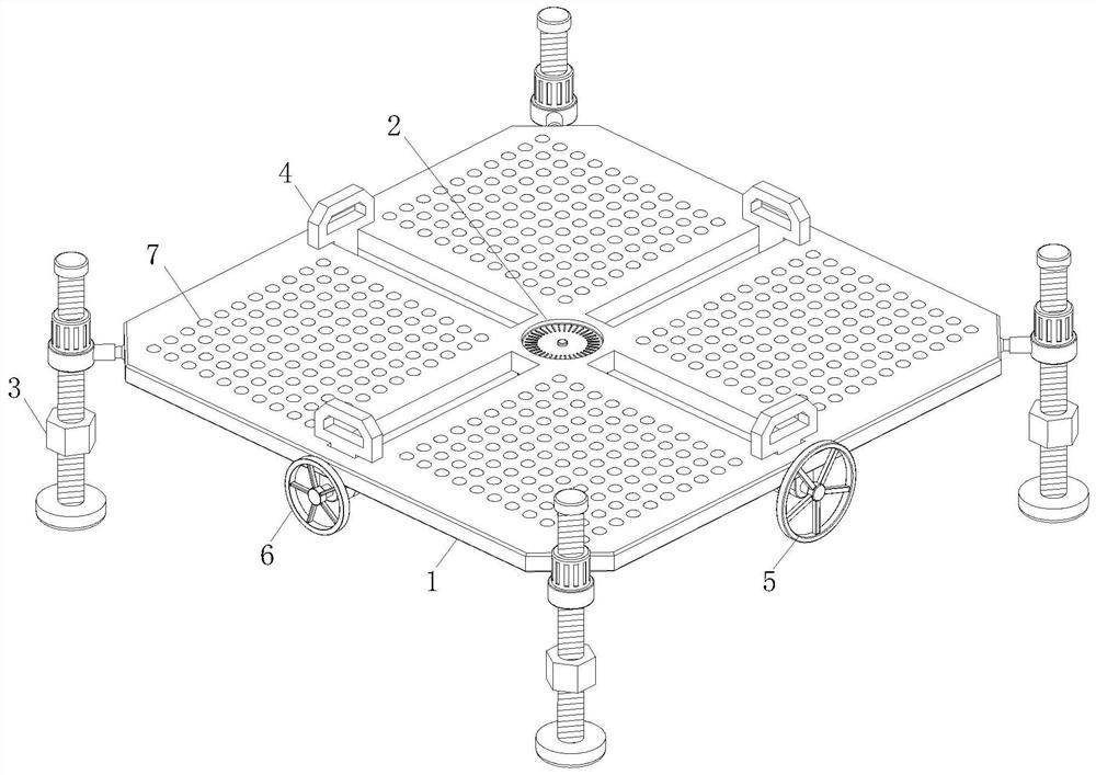
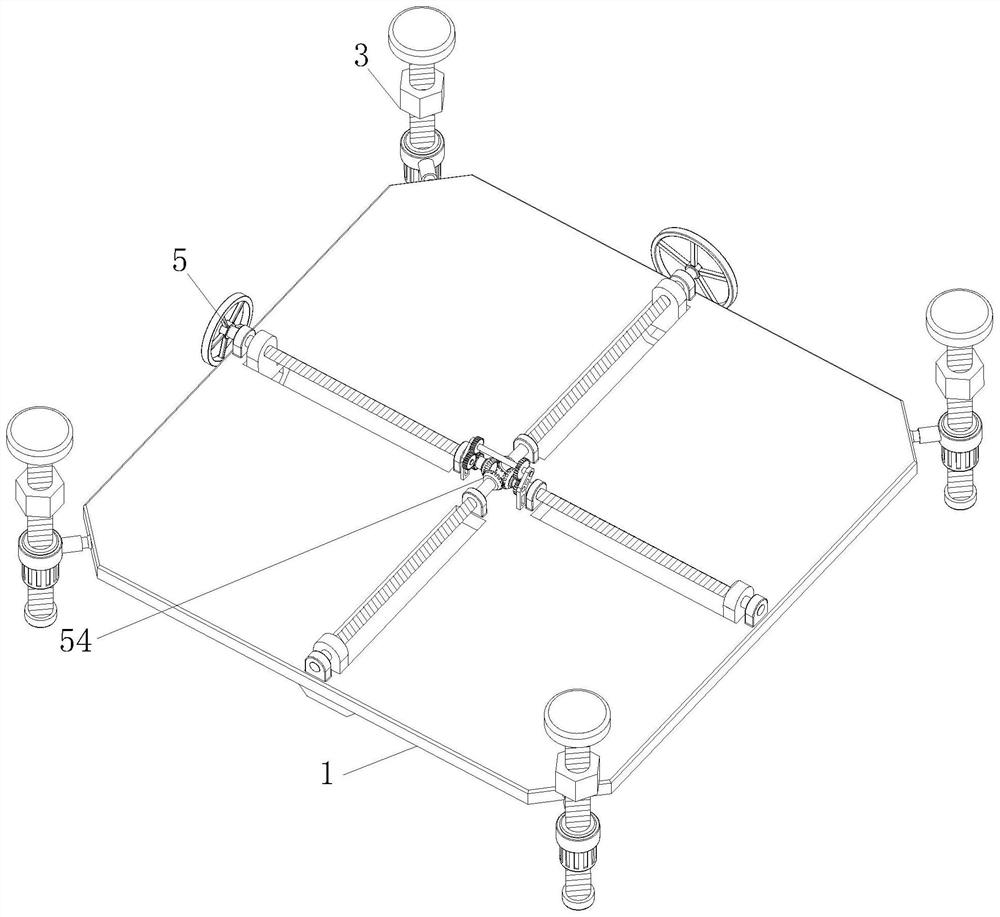
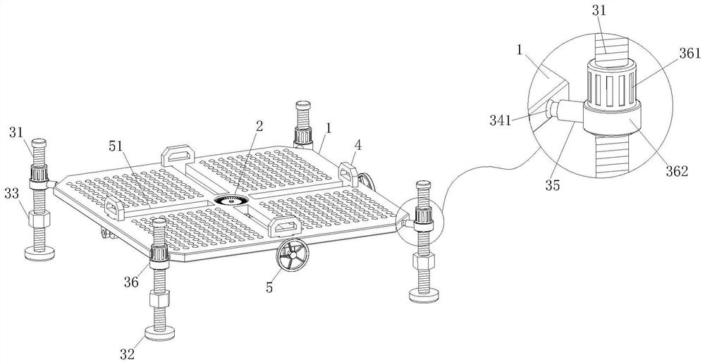
[0026] see Figure 1-5 , the present invention provides a technical solution: an auxiliary correction device for gantry processing equipment, including a bearing plate 1, the bearing plate 1 is a rectangular plate structure, but not limited thereto;

[0027] A bubble level 2 is installed in the middle of the bearing plate 1. During continuous use, the level of the bearing plate 1 can be monitored in real time through the bubble level 2 to ensure that each work...


PUM


Abstract

The invention discloses an auxiliary correction device for gantry machining equipment. The auxiliary correction device comprises a bearing plate, and a bubble level gauge is arranged in the middle of the bearing plate to monitor the levelness of the bearing plate in real time. According to the auxiliary correction device for the gantry machining equipment, through cooperative use of an arranged mounting component and the bubble level gauge, a mounting platform capable of continuously monitoring levelness can be provided, and horizontal clamping and machining of workpieces can be conveniently guaranteed; in addition, through cooperative use of positioning clamping plates, a synchronous driving component and an auxiliary driving component, when round and square workpieces are clamped and tidied up, the positioning clamping plates can be driven by the synchronous driving component to move synchronously, and the workpieces can be clamped synchronously and simultaneously from the sides; when irregular workpieces such as rectangular workpieces, trapezoid workpieces and the like are machined, the synchronous driving component drives the positioning clamping plates to move, the auxiliary driving component drives the other positioning clamping plates independently to independently and synchronously move and clamp the workpieces, and it is guaranteed that the workpieces in various shapes can be conveniently positioned, clamped, machined and used.

Description

technical field [0001] The invention relates to the technical field of gantry processing centers, in particular to an auxiliary calibration device for gantry processing equipment. Background technique [0002] With the development of the manufacturing industry, large-scale CNC gantry machining centers have been used more and more, and the gantry machining center includes columns standing on both sides of the bed, beams are fixed on the top of the columns, and sliding seats are movably connected to the rails of the beams , a ram is installed on the sliding seat, and a vertical main shaft mechanism and four slider assemblies are installed on the lower end of the ram, and the four slider assemblies are symmetrically distributed on the outer periphery of the vertical main shaft mechanism. [0003] For the detection and correction of the parallelism of the guide rails of the gantry machine tool, the current detection method is to install the special guide rail beam device on the ...

Claims


Application Information

Patent Timeline
Patent Type & Authority Applications(China)
IPC IPC(8): B23Q3/06B23Q17/00
CPCB23Q3/06B23Q17/00
Inventor 欧阳梦婕
Owner SHENZHEN CITY HUAQUN CNC MACHINERY
Features
  • R&D
  • Intellectual Property
  • Life Sciences
  • Materials
  • Tech Scout
  • Unparalleled Data Quality
  • Higher Quality Content
  • 60% Fewer Hallucinations
Learn More