
Visual evaluation device and method for motion state of machine tool group component

A motion state and component technology, applied in metal processing mechanical parts, measuring/indicating equipment, metal processing equipment, etc., can solve the problems of inconvenient adjustment of mechanical state, affecting the processing effect of the whole machine, poor operability, etc.

Pending Publication Date: 2021-07-06
LANGFANG JINGDIAO MACHINE TOOL MFG +1
View PDF10 Cites 0 Cited by
  • Summary
  • Abstract
  • Description
  • Claims
  • Application Information

AI Technical Summary

Problems solved by technology

[0002] The overall basic motion state of the machine tool is determined by the motion state of each moving part of the machine tool. Conventional three-axis equipment is generally composed of Z-axis motion components (ie, head parts), X-axis motion components (ie, beam components), and Y-axis motion components ( That is, the motion state of the bed parts) is determined by the motion state of the five-axis equipment. In addition to the above components, the five-axis equipment also includes four and five-axis components (ie, turntable components). If the basic state of any part is not good, it will affect the state of the linkage, and ultimately affect the processing of the whole machine. Effect
At present, most of the state evaluation of each group of components is to process the actual workpiece after assembling the whole machine, evaluate the motion state of the whole machine according to the processing effect, and then evaluate the basic motion state of the specific related moving parts through some detection methods. If it is necessary to adjust the group The mechanical state of the components is mostly operated in the online state of the whole machine or disassembled for offline adjustment. The operability is very poor, it is not convenient to adjust the mechanical state and affects the one-time success rate of the finished machine.

Method used


Image

  • Visual evaluation device and method for motion state of machine tool group component
  • Visual evaluation device and method for motion state of machine tool group component
  • Visual evaluation device and method for motion state of machine tool group component

Examples


Embodiment Construction

[0027] The present invention will be further described in detail below in conjunction with the accompanying drawings and specific embodiments.

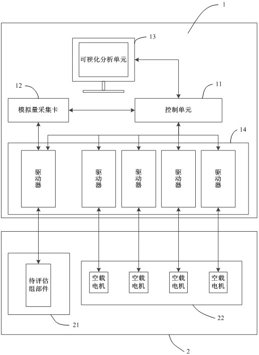
[0028] like figure 1 As shown, a visual evaluation device for the motion state of machine tool components of the present invention is composed of an electric control platform 1 and a component installation platform 2. The electric control platform 1 includes a control unit 11, an analog acquisition card 12, and a visual analysis unit 13 And the driver unit 14;

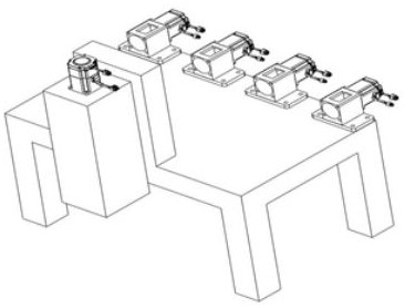
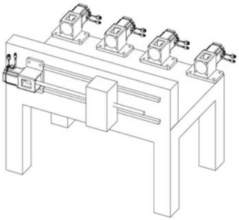
[0029] The component installation unit 21 is used to install the components to be evaluated, and the no-load motor installation unit 22 is used to install the no-load driving motors of other moving components of the machine tool except the components to be evaluated. The driver unit 14 is provided with the same number of drivers as the number of motion axes of the machine tool, which are respectively connected to the drive motors of the components to be evaluated and the no-l...


PUM


Abstract

The invention relates to a visual evaluation device and method for the motion state of a machine tool group component. The device is composed of a control unit, an analog quantity collection card, a visual analysis unit, a driver unit, a group component installation unit, and a no-load motor installation unit. A to-be-evaluated group component is arranged on the group component installation unit, and driving motors of other movement group components of a machine tool are respectively mounted on the no-load motor installation unit. The control unit controls the idle running-in workpiece machining path of no-load driving motors of the to-be-evaluated group component and other movement group components of the machine tool through the driver unit, dynamic load data of the driving motor of the to-be-evaluated group component are extracted through the analog quantity collection card, the control unit processes the dynamic load data, and displaying and analyzing are conducted in the visual analysis unit in a chromatogram form. According to the visual evaluation device and method, offline independent evaluation and adjustment of the motion state of the machine tool group components are realized, adjustment is convenient, and the one-time success rate of mounting the group components on the machine tool is effectively ensured.

Description

technical field [0001] The invention belongs to the field of mechanical manufacturing, and in particular relates to a visual evaluation device and method for the motion state of machine tool components. Background technique [0002] The overall basic motion state of the machine tool is determined by the motion state of each moving part of the machine tool. Conventional three-axis equipment is generally composed of Z-axis motion components (ie, head parts), X-axis motion components (ie, beam components), and Y-axis motion components ( That is, the motion state of the bed components) is determined by the motion state of the five-axis equipment. In addition to the above components, the five-axis equipment also includes four and five-axis components (ie, the turntable components). If the basic state of any component is not good, it will affect the state of the linkage, and ultimately affect the processing of the whole machine. Effect. At present, most of the state evaluation of...

Claims


Application Information

Patent Timeline
IPC IPC(8): B23Q17/00
CPCB23Q17/007Y02P90/02
Inventor 都学飞王春雷王金鹏吕乐张震震张硕武淼李红星邓永和
Owner LANGFANG JINGDIAO MACHINE TOOL MFG
Learn More