Linear guide rail-guided mold clamping mechanism compatible with various power combinations

A technology of linear guide rail and mold clamping, which is applied in the field of mold clamping mechanism and mold clamping mechanism of injection molding machine, which can solve the problems of prolonged delivery period, rising cost, and decreased service life of linear guide rail.

Pending Publication Date: 2021-07-06
BORCH MACHINERY
View PDF5 Cites 0 Cited by
  • Summary
  • Abstract
  • Description
  • Claims
  • Application Information

AI Technical Summary

Problems solved by technology

In order to meet the needs of customers, if these products are produced, different clamping modules need to be produced correspondingly, which increases the types of parts, prolongs the delivery cycle, and wastes production
[0003] In the existing mold locking mechanism, when the moving plate of the mold locking is guided by a linear guide rail, the slider of the linear guide rail is directly connected with the moving plate of the mold locking, which causes the upper and lower asymmetry of the moving plate of the mold locking
Moreover, the mold locking movable plate will definitely deform during the process of ge

Method used


Image

  • Linear guide rail-guided mold clamping mechanism compatible with various power combinations
  • Linear guide rail-guided mold clamping mechanism compatible with various power combinations
  • Linear guide rail-guided mold clamping mechanism compatible with various power combinations

Examples


Embodiment Construction

[0029] The technical solutions of the present invention will be clearly and completely described below in conjunction with the embodiments. Apparently, the described embodiments are only some of the embodiments of the present invention, not all of them. Based on the embodiments of the present invention, all other embodiments obtained by persons of ordinary skill in the art without creative efforts fall within the protection scope of the present invention.

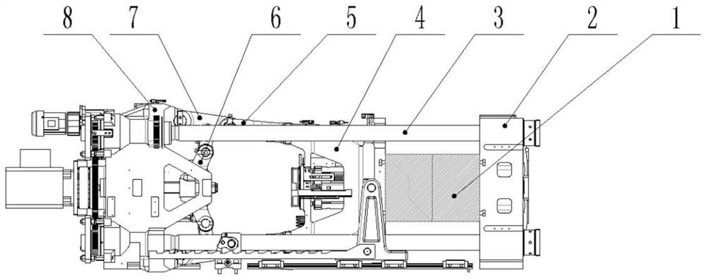
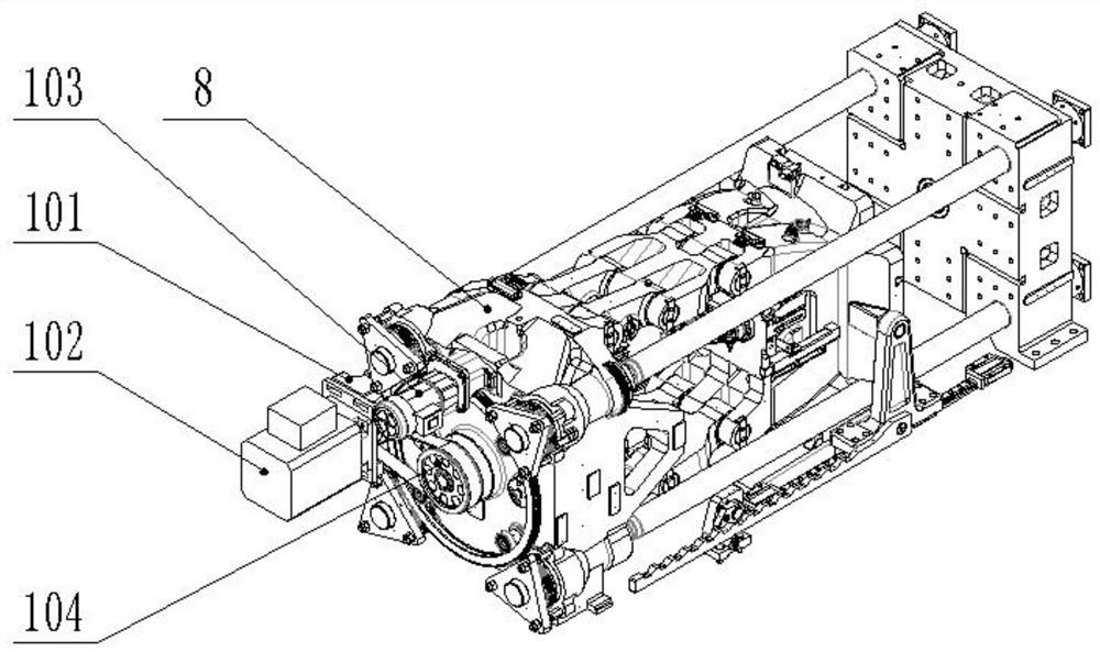
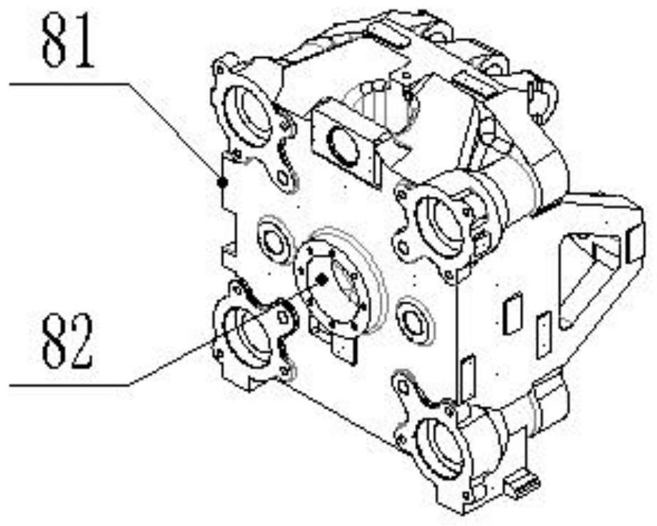
[0030] see Figure 1-10 As shown, a linear guide rail-guided mold clamping mechanism compatible with various power combinations includes a mold clamping fixed plate 2, a mold clamping moving plate 4 and a mold locking tail plate 8, and the mold locking moving plate 4 is located on the mold locking plate 2 and the clamping tail plate 8, the four corners of the clamping plate 2 are fixed with pull rods 3, the pull rods 3 pass through the clamping movable plate 4 and are fixedly installed on the clamping tail plate 8, the clam...


PUM


Abstract

The invention discloses a linear guide rail-guided mold clamping mechanism compatible with various power combinations. The mold clamping mechanism comprises a mold clamping fixed plate, a mold clamping movable plate and a mold clamping tail plate, wherein pull rods are fixedly arranged at four corners of the mold clamping fixed plate, the pull rods penetrate through the mold clamping movable plate and are fixedly arranged on the mold clamping tail plate, and a mold is placed between the mold clamping movable plate and the mold clamping fixed plate; and a first mounting interface and a second mounting interface are formed in the mold clamping tail plate, the first mounting interface and the second mounting interface are used for mounting a hydraulic power assembly and an electric power assembly separately, and the output end of the hydraulic power assembly and the output end of the electric power assembly are connected with the left end and the right end of a cross head separately. Through novel structure layout, the linear guide rail-guided mold clamping mechanism can be compatible with various power combinations, and can be compatible with hydraulic power or electric power under the condition that the main body structure is not changed. Therefore, any power combination is achieved, and the requirements of different products are met. A full-hydraulic mold clamping mechanism, a hybrid power mold clamping mechanism or a full-electric mold clamping mechanism is achieved.

Description

technical field [0001] The invention belongs to the technical field of mold clamping mechanisms for injection molding machines, and in particular relates to a mold clamping mechanism guided by linear guide rails compatible with various power combinations. Background technique [0002] The existing clamping mechanism can only use hydraulic power, or hybrid power, or one of all electric power. In order to meet customer needs, if these products are produced, different clamping modules need to be produced correspondingly, which increases the types of parts, prolongs the delivery cycle, and wastes production. [0003] In the existing mold locking mechanism, when the mold locking movable plate is guided by a linear guide rail, the slider of the linear guide rail is directly connected with the mold locking movable plate, causing the upper and lower asymmetry of the mold locking movable plate. Moreover, the mold locking movable plate will definitely deform during the process of gen...

Claims


Application Information

Patent Timeline
IPC IPC(8): B29C45/64B29C45/67
CPCB29C45/64B29C45/67
Inventor 孙晓波吴小廷袁中华杜呈表周清华刘媛
Owner BORCH MACHINERY
Why Eureka
Try Eureka