Hydrological monitoring buoy protection device

A protection device, hydrological monitoring technology, applied in buoys, collision avoidance, transportation and packaging, etc., can solve problems such as limited protection

Active Publication Date: 2021-07-06
河南章全机电设备有限公司
View PDF7 Cites 1 Cited by
  • Summary
  • Abstract
  • Description
  • Claims
  • Application Information

AI Technical Summary

Problems solved by technology

[0004] This research provides a reference for the design and use of buoy impact protection structu

Method used


Image

  • Hydrological monitoring buoy protection device
  • Hydrological monitoring buoy protection device
  • Hydrological monitoring buoy protection device

Examples


Embodiment 1

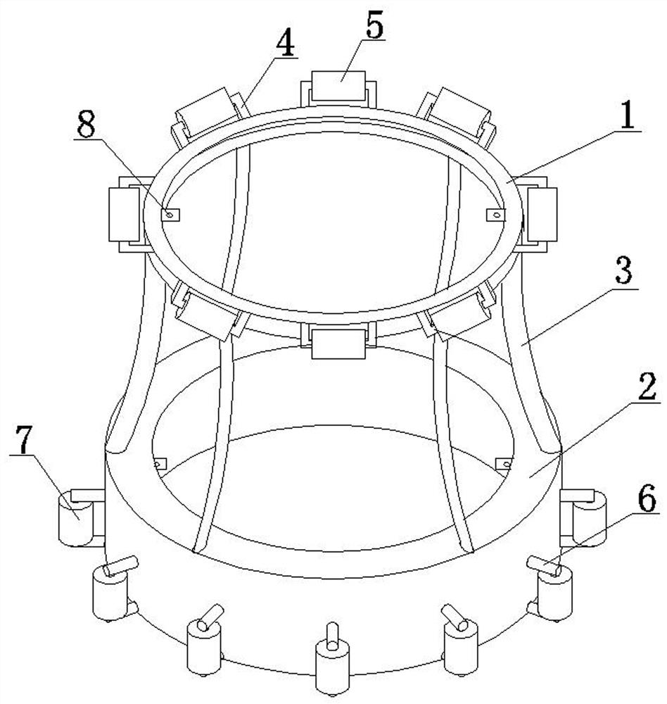
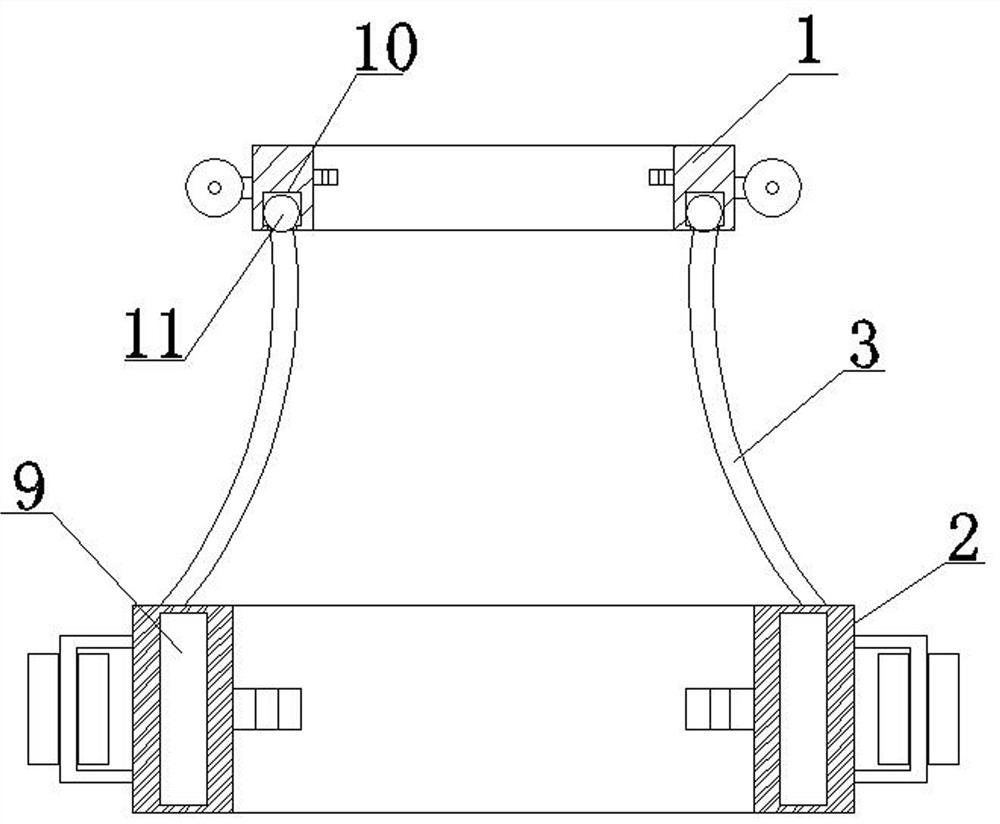
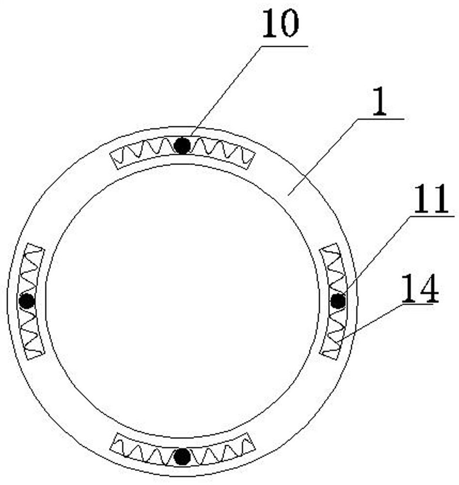
[0033] A hydrological monitoring buoy protection device, comprising a protective frame 1, a protective frame 2 2 and an arc-shaped support 3, the arc-shaped support 3 is movably connected with the lower part of the protective frame 1, and is fixedly connected with the upper part of the protective frame 2 2; the specific movable connection The method is as follows: a slideway 10 is set in the lower part of the protective frame-1, a slide block 11 matching the slideway 10 is set on the top of the arc-shaped support 3, and buffer springs 14 are set on both sides of the slide block 11, that is, under the action of an external force, the protective frame-1 There is a certain angle of rotation in the horizontal direction, and it can also be reset under the action of the buffer spring 14.

[0034] The outer wall of the protective frame-1 is evenly distributed with transverse brackets 4, and the rollers-5 are sleeved on the transverse brackets 4. Therefore, when subjected to impact fro...

Embodiment 2

[0046] The difference between embodiment 2 and embodiment 1 is that the composite aluminum foam material is prepared by the following steps:

[0047] (1) Ingredients: Mg 1.2wt%, Si 0.6wt%, Ca 0.8wt%, Ti 1.2wt%, Cr 0.4wt%; the balance is Al;

[0048] Mix the above-mentioned Mg, Si, Al, Ti and Cr according to the ratio, heat and melt to form an alloy melt, and keep it warm for 30 minutes;

[0049] (2) Cool down to 720°C, add Ca and a small amount of AlN and glass fiber, and stir for 5-8 minutes;

[0050] (3) When the composite melt temperature reaches 690°C, add 1.5wt% blowing agent TiH to the composite melt 2 , stirred for 2 minutes, continued heat preservation and foaming for 10 minutes, and cooled to obtain the product.

[0051] The amount of AlN added is 4wt% of aluminum.

[0052] The compressive yield strength of the composite aluminum foam material sample prepared above was detected to be 35 MPa, and the porosity was 75%.

Embodiment 3

[0054] The difference between embodiment 3 and embodiment 1 is that the composite aluminum foam material is prepared by the following steps:

[0055] (1) Ingredients: Mg 1.3wt%, Si 0.8wt%, Ca 0.6wt%, Ti 1.5wt%, Cr 0.45wt%; the balance is Al;

[0056] Mix the above-mentioned Mg, Si, Al, Ti and Cr according to the ratio, heat and melt to form an alloy melt, and keep it warm for 30 minutes;

[0057] (2) Cool down to 720°C, add Ca and a small amount of AlN and glass fiber, and stir for 5-8 minutes;

[0058] (3) When the composite melt temperature reaches 700°C, add 1.8wt% blowing agent TiH to the composite melt 2 , stirred for 2 minutes, continued heat preservation and foaming for 10 minutes, and cooled to obtain the product.

[0059] The amount of AlN added is 4wt% of aluminum.

[0060] The compressive yield strength of the composite aluminum foam material sample prepared above was detected to be 32 MPa, and the porosity was 78%.


PUM

PropertyMeasurementUnit
Diameteraaaaaaaaaa
Lengthaaaaaaaaaa
Compressive yield strengthaaaaaaaaaa

Abstract

The invention discloses a hydrological monitoring buoy protection device. The device comprises a first protection frame, a second protection frame and an arc-shaped support, and the arc-shaped support is movably connected with the lower portion of the first protection frame and fixedly connected with the upper portion of the second protection frame; transverse supports are evenly distributed on the outer wall of the first protection frame and sleeved with first rollers, vertical supports are evenly distributed on the outer wall of the second protection frame and sleeved with second rollers, and mounting holes are formed in the inner wall of the first protection frame and the inner wall of the second protection frame. A buffer layer is arranged in the second protection frame. The structure and materials of the protection device are improved, and the anti-impact protection effect is excellent.

Description

technical field [0001] The invention relates to the technical field of hydrological monitoring, in particular to a protective device for a hydrological monitoring buoy. Background technique [0002] Hydrological monitoring buoys are an important tool for detecting ocean water bodies. The parameters of hydrological monitoring include temperature and humidity, air pressure, wind speed, salinity, wave elements, and water quality parameters. Therefore, the main structures of buoys include buoys, frames, power supply equipment, and sensors. , data acquisition equipment, mooring systems and protective equipment, etc., because the buoy has been floating in the ocean for a long time, it is easy to be washed by waves and impacted by external forces such as fishing boats and marine life, which may cause damage or shift its original position. Therefore, buoy protection Devices are critical. [0003] There are also many studies on buoy protection in the existing technology. For example...

Claims


Application Information

Patent Timeline
IPC IPC(8): B63B22/00B63B43/18C22C49/06C22C47/08C22C49/14C22C101/06
CPCB63B22/00B63B43/18C22C49/06C22C49/14C22C47/08B63B2022/006B63B2043/185Y02A30/30
Inventor 李任朋
Owner 河南章全机电设备有限公司
Why Eureka
Try Eureka