Aerobic and anaerobic combined garbage fermentation device

A fermentation device and aerobic fermentation technology, applied in the field of garbage fermentation equipment, can solve problems such as inconvenient use, environmental pollution, unfavorable aerobic fermentation, etc.

Inactive Publication Date: 2021-07-06
王晨仪
View PDF0 Cites 1 Cited by
  • Summary
  • Abstract
  • Description
  • Claims
  • Application Information

AI Technical Summary

Problems solved by technology

[0003] Due to the different environments required for anaerobic fermentation and aerobic fermentation, the existing garbage fermentation treatment devices usually only have one fermentation method, and it is not possible to use different fermentation devices to ferment garbage in different environments, only a single The use of a fermentation method is not convenient enough to use;
[0004] Moreover, when the anaerobic fermentation device ferments garbage, waste gas will generally be generated. Existing anaerobic fermentation devices generally do not have a waste gas treatment device. If the waste gas is directly discharged into the atmosphere, it will pollute the environment. Not convenient enough to use;
[0005] When the aerobic fermentation device is fermenting the garbage, because it needs to feed gas into the aerobic fermentation tank, when the garbage is injected into the aerobic fermentation tank, the garbage in the aerobic fermentation tank may cause the blockage of the air hole , so that the gas cannot pass into the aerobic fermentation tank, which is very unfavorable for aerobic fermentation and reduces the efficiency of garbage fermentation to a certain extent;

Method used


Image

  • Aerobic and anaerobic combined garbage fermentation device
  • Aerobic and anaerobic combined garbage fermentation device
  • Aerobic and anaerobic combined garbage fermentation device

Examples


Embodiment Construction

[0030] The following will clearly and completely describe the technical solutions in the embodiments of the present invention with reference to the accompanying drawings in the embodiments of the present invention. Obviously, the described embodiments are only some, not all, embodiments of the present invention. The specific embodiments described here are only used to explain the present invention, not to limit the present invention. Based on the embodiments of the present invention, all other embodiments obtained by persons of ordinary skill in the art without making creative efforts belong to the protection scope of the present invention.

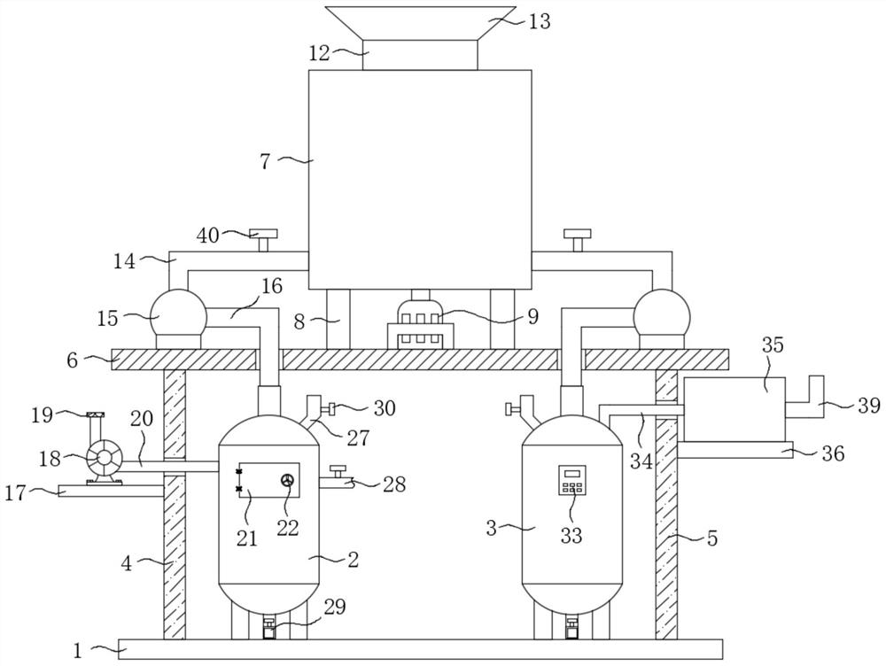
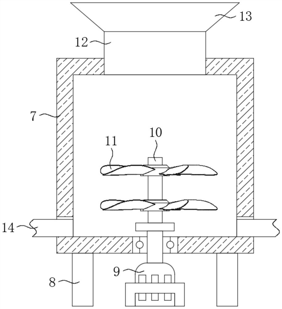
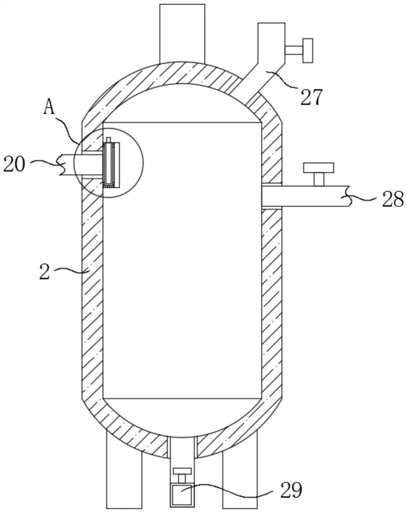
[0031] The present invention provides such Figure 1-7 The shown aerobic-anaerobic combined garbage fermentation device includes a substrate 1, and an aerobic fermentation tank 2 and an anaerobic fermentation tank 3 are fixedly installed on the upper end of the substrate 1, and the aerobic fermentation tank 2 and the anaerobic fermentatio...


PUM


Abstract

The invention discloses an aerobic and anaerobic combined garbage fermentation device. The device comprises a base plate, an aerobic fermentation tank and an anaerobic fermentation tank are fixedly mounted at the upper end of the base plate, a fixing frame is fixedly connected to the inner wall of the aerobic fermentation tank, and the fixing frame is arranged at the communicating position of a gas conveying pipe and the aerobic fermentation tank. A filter plate is arranged in the fixing frame, and the upper end of the anaerobic fermentation tank communicates with a purification box through a first gas outlet pipe. When the device is used, the aerobic fermentation tank and the anaerobic fermentation tank are simultaneously arranged at the upper end of the base plate, so that different fermentation devices can be conveniently selected to ferment garbage in different environments; and the purification box is arranged at the gas outlet end of the anaerobic fermentation tank, and used for purifying waste gas generated when the anaerobic fermenter ferments garbage. A filter screen is arranged at a vent hole of an aerobic fermentation tank, so that the vent hole can be prevented from being blocked by the garbage, and use is very convenient.

Description

technical field [0001] The invention belongs to the technical field of garbage fermentation equipment, and in particular relates to an aerobic-anaerobic combination garbage fermentation device. Background technique [0002] The composting method to treat domestic waste refers to the method of decomposing, decomposing, and converting the organic matter in domestic waste into stable humus-like soil by virtue of the biochemical action of microorganisms under artificial control conditions. The principle of composting can be roughly divided into two types: anaerobic fermentation and aerobic fermentation. Anaerobic fermentation is to reduce garbage or completely isolate it from the air, and use anaerobic bacteria to decompose organic matter to produce carbon dioxide, water, methane and humus. The process of soil; aerobic fermentation is a method of turning over the pile, forced ventilation, and using aerobic bacteria to decompose organic matter to stabilize it. The products are ca...

Claims


Application Information

Patent Timeline
IPC IPC(8): C12M1/12C12M1/00
CPCC12M29/04C12M29/20C12M47/18
Inventor 王晨仪
Owner 王晨仪
Why Eureka
Try Eureka