
Pile-beam integrated fully-prefabricated assembled bridge substructure, bridge and construction method thereof

A technology of prefabricated assembly and construction method, applied in infrastructure engineering, erection/assembly of bridges, bridges, etc., can solve problems such as high material consumption, many on-site procedures, and easy environmental pollution.

Pending Publication Date: 2021-07-06
GUANGDONG PROVINCE COMM PLANNING & DESIGN INST
View PDF0 Cites 0 Cited by
  • Summary
  • Abstract
  • Description
  • Claims
  • Application Information

AI Technical Summary

Problems solved by technology

However, the construction of traditional bridges cannot meet the requirements of rapid construction. The reason is that most traditional bridges use pier-column lower parts, which are connected to the upper structure through cover beams, and adopt the cast-in-place construction method. The following problems exist in the construction process: 1. The large number of on-site labor force does not adapt to the development trend of an aging society, and there are safety risks for on-site personnel; 2. There are many on-site procedures and high material consumption, resulting in waste of resources; 3. It is difficult to guarantee the quality of on-site pouring; 4. Construction waste Many, easy to pollute the environment, easy to cause traffic congestion; 5. The construction temporarily occupies a large area, and sometimes it is necessary to build temporary access roads, temporary access bridges, etc.

Method used


Image

  • Pile-beam integrated fully-prefabricated assembled bridge substructure, bridge and construction method thereof
  • Pile-beam integrated fully-prefabricated assembled bridge substructure, bridge and construction method thereof
  • Pile-beam integrated fully-prefabricated assembled bridge substructure, bridge and construction method thereof

Examples


Embodiment Construction

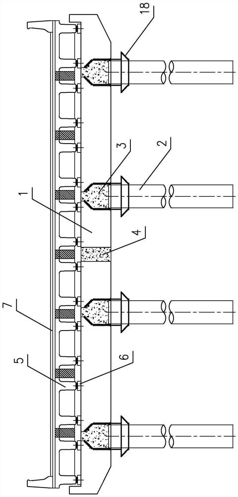
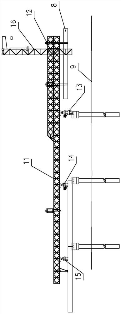
[0035] Such as figure 1 Shown is a pile-beam integrated fully prefabricated assembled bridge substructure of the present invention, which includes a cover beam 1 and a pier column, the cover beam 1 is arranged along the transverse bridge direction, and the pier column is poured in the pile core of the prefabricated concrete pipe pile The precast concrete pipe pile 2 made of concrete, the lower end of the precast concrete pipe pile 2 is fixed in the foundation, the connection node 3 between the upper end and the cover beam 1 and the precast concrete pipe pile 2 are formed by one-time pouring of concrete, so that the prefabricated The concrete pipe pile column 2 is connected with the cover beam 1 as a whole.

[0036] Specifically, a vertical through hole is reserved on the cover beam 1, and a temporary steel hoop 18 is set on the upper end of the precast concrete pipe pile. The cage is inserted into the reserved hole and extends into the prefabricated concrete pipe pile, and th...


PUM


Abstract

The invention discloses a pile-beam integrated fully-prefabricated assembled bridge substructure, a bridge and a construction method thereof.The pile-beam integrated fully-prefabricated assembled bridge substructure comprises a cover beam and a pier stud, the cover beam is arranged in the transverse bridge direction, and the pier stud is a prefabricated concrete pipe pile column formed by pouring concrete in a pile core of a prefabricated concrete pipe pile; the connecting joint of the upper end of the prefabricated concrete pipe pile column and the cover beam and the prefabricated concrete pipe pile column are formed by one-time concrete pouring. According to the invention, a full-prefabricated assembly concept is adopted, so that the integrated installation of the prefabricated concrete pipe pile column, the cover beam and the main beam can be realized. The construction method is easy to operate, convenient to construct, safe and reliable, the construction progress can be accelerated, the construction cost can be reduced, existing road transportation pipe piles can be utilized, construction shortcuts and construction temporary bridges do not need to be erected, occupied space is saved, good adaptability is achieved for regions with high construction environment requirements, and the construction method can be applied to the environment where the construction conditions are limited and shortcuts and temporary bridges cannot be erected. And full-prefabricated industrial construction and quick construction can be realized in urban regions with busy traffic.

Description

technical field [0001] The invention belongs to the prefabricated assembly technology of road and municipal road bridges, and in particular relates to a pile-beam integrated bridge substructure, and also relates to a bridge including the pile-beam integrated bridge substructure and a construction method thereof. Background technique [0002] With the rapid development of my country's economy in recent years, industrialized construction and rapid construction of bridges have gradually become the development direction of the construction industry, especially in densely populated urban areas or across busy roads. However, the construction of traditional bridges cannot meet the requirements of rapid construction. The reason is that most traditional bridges use pier-column lower parts, which are connected to the upper structure through cover beams, and adopt the cast-in-place construction method. The following problems exist in the construction process: 1. The large number of on-...

Claims


Application Information

Patent Timeline
IPC IPC(8): E01D19/00E01D19/02E01D19/06E01D2/00E01D21/00E02D5/30E02D7/06E01D101/24E01D101/26
CPCE01D2/00E01D19/00E01D19/02E01D19/067E01D21/00E01D2101/24E01D2101/26E02D5/30E02D7/06E02D2300/002
Inventor 孙向东卢绍鸿黄国清姜启珍陈焕煜邱志雄刘敏刘国兴牟键超武继民
Owner GUANGDONG PROVINCE COMM PLANNING & DESIGN INST
Learn More