Concrete grouting and vibrating device
A vibrating device and concrete technology, which are applied in construction, building structure, construction material processing, etc., can solve problems such as emptiness, reducing the quality of concrete components, and inability to effectively fill gaps in concrete aggregates.
- Summary
- Abstract
- Description
- Claims
- Application Information
AI Technical Summary
Problems solved by technology
Method used
Image

Examples
Embodiment 1
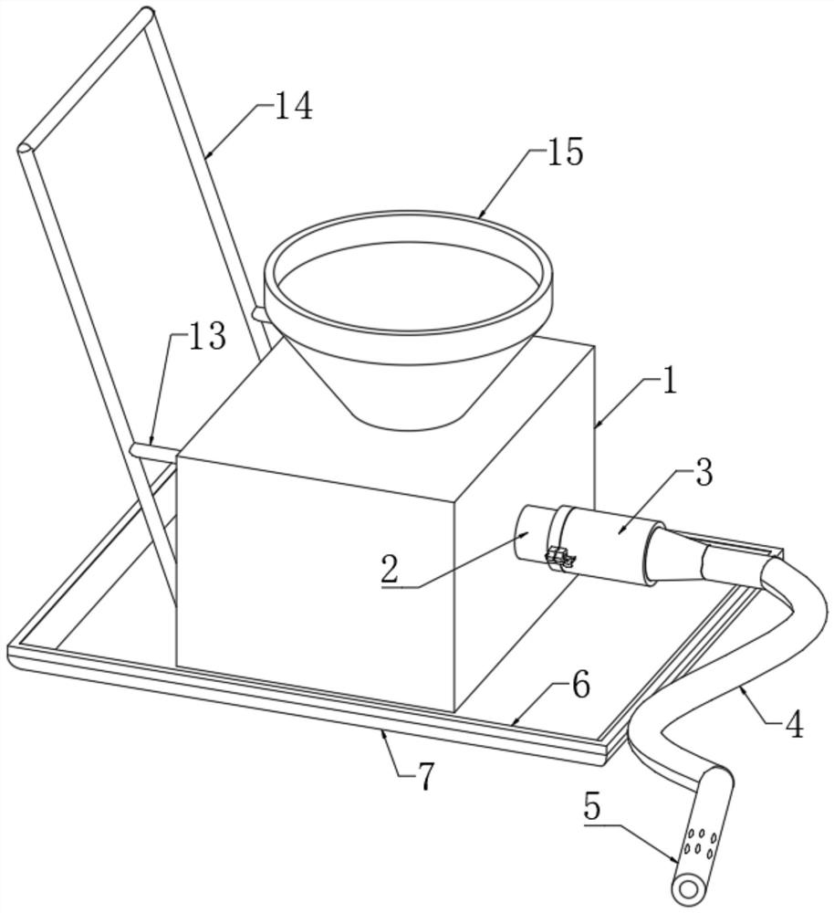
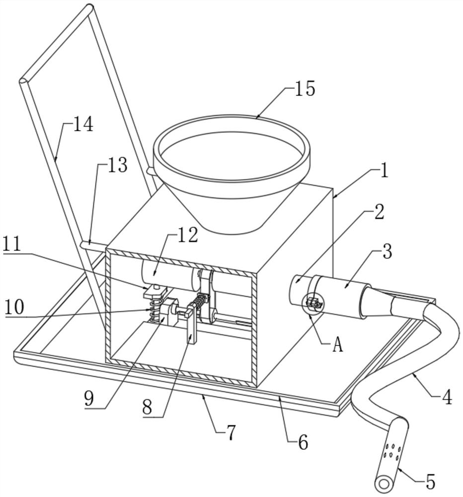
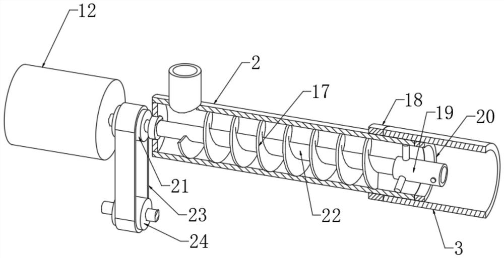
[0028] refer to Figure 1 to Figure 7, a concrete grouting and vibrating device, comprising a box body 1 and a vibrating rod joint 19, the right end of the box body 1 is fixedly connected with a horizontal tube 2 through a round hole, and the inner edge of the left end of the horizontal tube 2 is fixedly connected with a circular plate One side of the circular plate is rotatably connected with a transmission shaft 22 through a sealed bearing, and the shaft wall of the transmission shaft 22 is fixedly connected with a helical blade 17, and one end of the transmission shaft 22 is fixedly connected with the vibrating rod joint 19, and the shell of the vibrating rod joint 19 It is fixedly connected with the inner wall of the horizontal tube 2, and the nozzle at the right end of the horizontal tube 2 is connected with a casing 3 through a connecting mechanism, and the right end of the casing 3 is fixedly connected with a flexible conduit 4, and one end of the flexible conduit 4 is f...
Embodiment 2
[0030] Embodiment 2: the difference based on Embodiment 1 is;
[0031] refer to Figure 4 and Figure 5 , the connecting mechanism includes two fixed blocks 32, and the two fixed blocks 32 are symmetrically fixed on the outer edge of one end of the casing 3, and one side of the fixed block 32 is connected with a shaft pin 33 through a positioning hole, and the shaft pin 33 The shaft wall is fixedly connected with a positioning ring, one end of the shaft pin 33 is fixedly connected with a brake lever 31, the other end of the shaft pin 33 is fixedly connected with a positioning block 35, and the tube wall of the horizontal tube 2 is fixedly connected with a positioning ring 18. The side wall of the ring 18 is symmetrically fixedly connected with two clamping blocks 34, and the side walls of the two clamping blocks 34 are provided with through holes, and one side of the through hole is provided with a through groove, and the through groove matches with the positioning block 35. ...
Embodiment 3
[0033] Embodiment 3: the difference based on embodiment 1 is;
[0034] refer to Figure 6 , the vibrating mechanism includes two rectangular blocks 9, the two rectangular blocks 9 are slidingly socketed in the bar-shaped through-hole, the lower end of the rectangular block 9 passes through the bar-shaped through-hole and is fixedly connected with a horizontal plate 7, and the box body 1 is equipped with There is a rotating shaft 26, and the two ends of the rotating shaft 26 are respectively connected to the opposite sides of the two rectangular blocks 9 through rolling bearings. The shaft wall of the rotating shaft 26 is symmetrically fixedly connected with two counterweights 27. A first pulley 24 is fixedly connected to the shaft wall, a second pulley 21 is fixedly connected to the shaft wall of the rotating shaft, and a belt 23 is connected between the first pulley 24 and the second pulley 21. The inner walls of the left and right ends of the box body 1 Both are fixedly con...
PUM
 Abstract
Description
Claims
Application Information
 - R&D
- Intellectual Property
- Life Sciences
- Materials
- Tech Scout
- Unparalleled Data Quality
- Higher Quality Content
- 60% Fewer Hallucinations
Browse by: Latest US Patents, China's latest patents, Technical Efficacy Thesaurus, Application Domain, Technology Topic, Popular Technical Reports.
© 2025 PatSnap. All rights reserved.Legal|Privacy policy|Modern Slavery Act Transparency Statement|Sitemap|About US| Contact US: help@patsnap.com