Device and method for collecting water sample at specified depth in drill hole

A collection device and technology in a borehole, which are applied in the field of deep water sample collection devices in boreholes, and can solve problems such as collision damage to the borehole wall, poor working reliability, and inability to accurately collect water samples at a specified depth.

Active Publication Date: 2021-07-06
INST OF KARST GEOLOGY CAGS
View PDF33 Cites 1 Cited by
  • Summary
  • Abstract
  • Description
  • Claims
  • Application Information

AI Technical Summary

Problems solved by technology

[0006] In view of the above analysis, the present invention aims to provide a device and method for collecting internally fixed deep water samples in boreholes, which are used to solve the problem of low sampling efficiency and poor functionality of existing internally fixed deep water sample collection devices for boreholes, which cannot accurately collect water samples at specified depths. Moreover, the device is easily displaced within the borehole during the sampling process, resulting in one or more of the problems of collision with the borehole wall, damage, short service life, and poor operational reliability.

Method used


Image

  • Device and method for collecting water sample at specified depth in drill hole
  • Device and method for collecting water sample at specified depth in drill hole
  • Device and method for collecting water sample at specified depth in drill hole

Examples


Embodiment 1

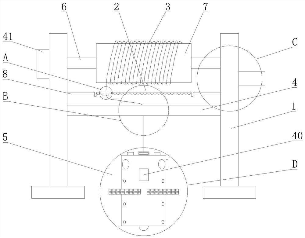
[0055] A specific embodiment of the present invention discloses a deep water sample collection device in a borehole, such as figure 1 shown, including:

[0056] Mounting frame 1, the mounting frame 1 is used to support the collection device;

[0057] Collection assembly 5, collection assembly 5 comprises collection cylinder 20 and liquid level sensor 26, and collection cylinder 20 has a plurality of independent collection chambers, and collection chamber is provided with air extraction port 22, sample inlet 37 and sample outlet 25, through air extraction port 22 pump air to form a negative pressure in the collection chamber, and the sample inlet 37 is provided with a sample inlet switch assembly 23, and the sample collected is taken out by the sample outlet 25; the liquid level sensor 26 is fixed on the collection cylinder 20, and through Monitoring data acquisition water sample collection depth;

[0058] The take-up and pay-off mechanism, the take-up and pay-off mechanism i...

Embodiment 2

[0087] On the basis of the foregoing embodiments, the present invention proposes a deep water sample collection device in a borehole, further comprising a buffer 27, the buffer 27 is arranged on the peripheral wall of the collection cylinder 20, and the shock absorber 27 is arranged to reduce the contact with the wall of the borehole. The impact force plays a protective role.

[0088] Such as Figure 8 As shown, the buffer 27 includes a buffer frame 28, a telescopic element 29 and an elastic pad 30, the buffer frame 28 is arranged on the periphery of the collection tube 20, the height of the buffer frame 28 is greater than or equal to the height of the collection tube 20, and the elastic pad 30 is arranged on the buffer frame 28 away from the end of the collection tube 20, the buffer frame 28 is connected to the peripheral wall of the collection tube 20 through a telescopic piece 29, and the telescopic piece 29 can elastically contract under impact. When the collection tube 2...

Embodiment 3

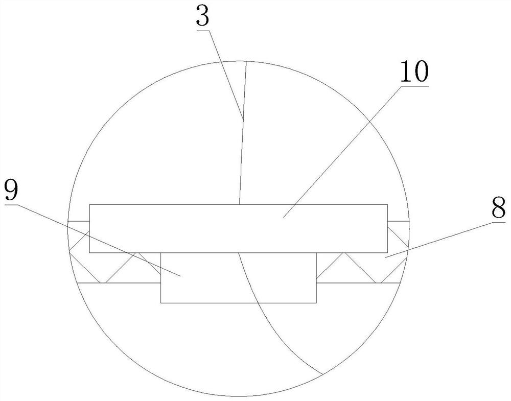
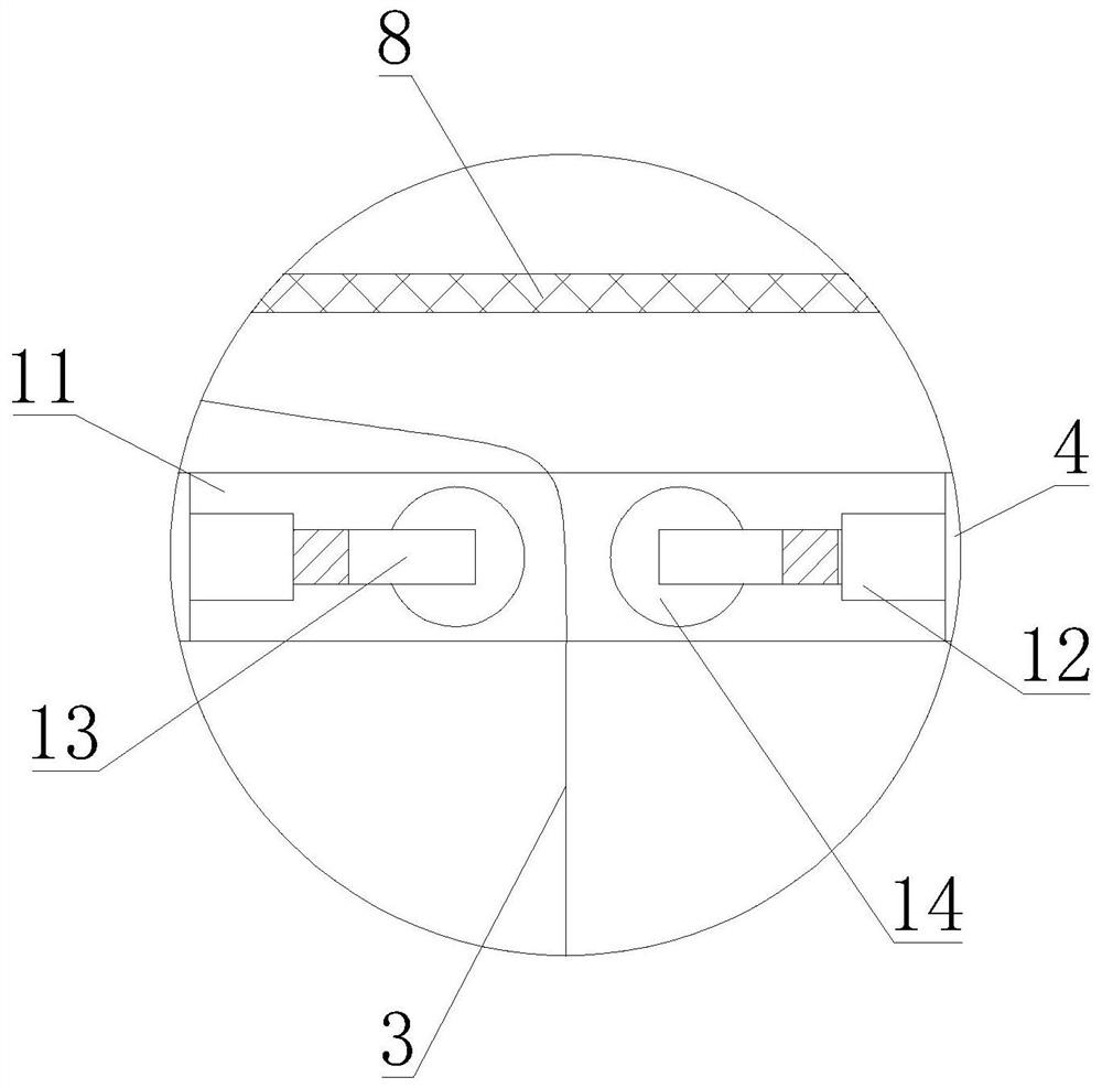
[0098] Such as Figure 4 As shown, on the basis of the above-mentioned embodiments, the present invention proposes a deep water sample collection device in a borehole. The assembly can simultaneously drive the rotating shaft 6 (that is, drive the winding roller 7 to rotate) and the lead screw 8 to rotate. Specifically, the second drive motor 16 is arranged on the mounting frame 1, and the mounting frame 1 is provided with a mounting cavity 15. The second The main shaft of the driving motor 16 extends into the installation cavity 15, and is bonded to the second gear 18; the rotating shaft 6 is arranged in parallel with the lead screw 8, and one end of the rotating shaft 6 and the lead screw 8 extends into the installation cavity 15, and is respectively bonded and connected The first gear 17 and the third gear 19 ; the first gear 17 and the third gear 19 are engaged with the second gear 18 respectively. That is to say, the first end of the rotating shaft 6 extends into the inst...


PUM


Abstract

The invention relates to a device and method for collecting a water sample at a specified depth in a drill hole, and belongs to the technical field of water sample collection. The problems of low sampling efficiency and poor working reliability of an existing collecting device are solved. The collecting device comprises a mounting frame, a collecting assembly, a take-up and pay-off mechanism and a controller, the collecting assembly comprises a collecting cylinder with a plurality of collecting chambers, each collecting chamber is provided with an extraction opening, a sample inlet and a sample outlet, and the sample inlet is provided with a sample inlet switch assembly; a liquid level sensor is arranged on the collecting cylinder; a winding roller of the take-up and pay-off mechanism is rotationally arranged on the mounting frame, the first end of a pull wire is wound around the winding roller, the second end of the pull wire penetrates through a wire guiding assembly to be connected with the collecting assembly, the driving assembly is used for driving the winding roller to rotate so as to achieve take-up and pay-off of the pull wire, and the wire guiding assembly is used for enabling the collecting assembly to be located on the center line of the drill hole; and the controller is in communication connection with the driving assembly and the sample inlet switch assembly. The collecting device is simple in structure, convenient to operate, capable of accurately collecting the water sample at the specified depth and high in sampling efficiency.

Description

technical field [0001] The invention relates to the field of water sample collection equipment, in particular to a device and method for collecting deep water samples in boreholes. Background technique [0002] Hydrogeology, a branch of geology, refers to the various changes and movements of groundwater in nature. Hydrogeology is the science of studying groundwater. It mainly studies the distribution and formation of groundwater, the physical properties and chemical composition of groundwater, and the groundwater. Resources and their rational utilization, the adverse effects of groundwater on engineering construction and mining and their prevention and control, etc. With the development of science and the needs of production and construction, hydrogeology is divided into regional hydrogeology, groundwater dynamics, hydrogeochemistry , water supply hydrogeology, ore deposit hydrogeology, soil improvement hydrogeology and other branch disciplines. [0003] In order to obtain ...

Claims


Application Information

Patent Timeline
IPC IPC(8): E21B49/08E21B47/047E21B23/14B01D35/02B01D29/64
CPCE21B49/082E21B23/14B01D35/02B01D29/6415B07B2201/04Y02A90/30
Inventor 任坤潘晓东彭聪焦友军曾洁梁嘉鹏
Owner INST OF KARST GEOLOGY CAGS
Why Eureka
Try Eureka