
Diffusers, fans and vacuum cleaners

A diffuser device and casing technology, which is applied to vacuum cleaners, machines/engines, components of pumping devices for elastic fluids, etc., can solve problems such as large energy loss and large noise, and reduce energy loss and noise , improve the effect of boundary layer separation

Active Publication Date: 2022-05-13
GUANGDONG WELLING ELECTRIC MACHINE MFG
View PDF0 Cites 0 Cited by
  • Summary
  • Abstract
  • Description
  • Claims
  • Application Information

AI Technical Summary

Problems solved by technology

[0003] The purpose of the embodiments of the present application is to provide a diffuser device to solve the problems in the related art that the airflow generated by the fan impeller tends to generate relatively large noise and large energy loss in the diffuser

Method used


Image

  • Diffusers, fans and vacuum cleaners
  • Diffusers, fans and vacuum cleaners
  • Diffusers, fans and vacuum cleaners

Examples


Embodiment Construction

[0028] In order to make the technical problems, technical solutions and beneficial effects to be solved by the present application clearer, the present application will be further described in detail below in conjunction with the accompanying drawings and embodiments. It should be understood that the specific embodiments described here are only used to explain the present application, and are not intended to limit the present application.

[0029] It should be noted that the terms "first" and "second" are only used for descriptive purposes, and cannot be understood as indicating or implying relative importance or implicitly indicating the quantity of indicated technical features. Thus, a feature defined as "first" and "second" may explicitly or implicitly include one or more of these features. In the description of the present application, "plurality" means two or more, unless otherwise specifically defined. "Several" means one or more than one, unless otherwise clearly and s...


PUM


Abstract

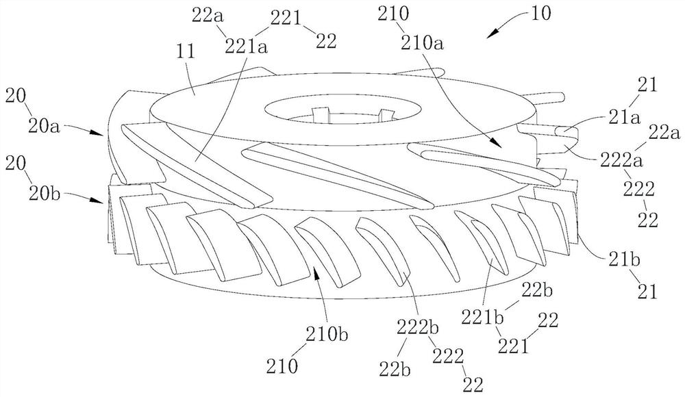
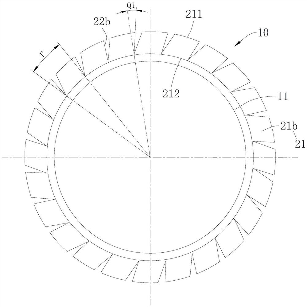
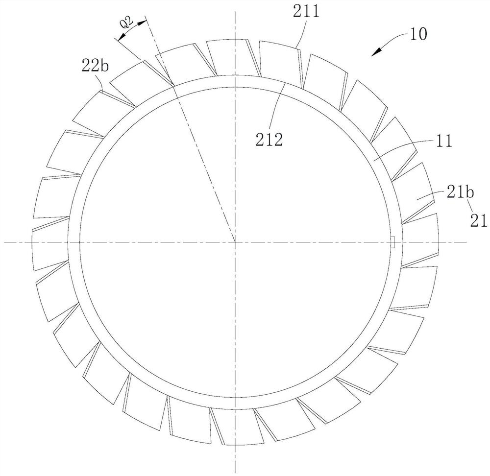
The application provides a diffuser device, fan and vacuum cleaner; the diffuser device includes a base and multiple rows of stationary vanes, the multiple rows of stationary vanes are arranged in sequence along the axial direction of the base, and there are multiple stationary vanes in each row, and A plurality of stator blades in each row are arranged along the circumference of the base, and the cross section of the base is circular; the profile of each stator blade in at least one row of the plurality of rows of stator blades is inclined toward one side of the stator blade. The diffuser device provided by this application is provided with multiple rows of stationary vanes in the circumferential direction of the base, and the airflow is gradually guided by the multiple rows of stationary vanes to reduce the absolute speed of the airflow to improve the supercharging effect; and at least one row of stationary vanes is of the type Tilting towards one side can effectively improve boundary layer separation and gas vortex flow between stator blades, thereby reducing energy loss and aerodynamic noise.

Description

technical field [0001] The present application belongs to the technical field of fans, and more specifically relates to a diffuser device, a fan using the diffuser device and a vacuum cleaner using the fan. Background technique [0002] At present, the fans used in hand-held vacuum cleaners and other equipment have the characteristics of small size and high speed (generally between 60,000 and 150,000 rpm). The motors of these fans drive the impellers to rotate. The airflow is sucked in from the inlet of the windshield. After obtaining a large kinetic energy through the impellers, it flows into the axial diffuser from the edge of the impellers along the radial direction of the impellers, and then flows out through the casing. The inlet of the wind hood forms a relatively large vacuum. When the airflow passes through the diffuser from the impeller, the interference area at the front end of the diffuser and the interior of the diffuser generate relatively large noise and large...

Claims


Application Information

Patent Timeline
Patent Type & Authority Patents(China)
IPC IPC(8): F04D29/44F04D29/66A47L5/22
CPCF04D29/444F04D29/667A47L5/22
Inventor 蒋婷婷冯国平龚黎明
Owner GUANGDONG WELLING ELECTRIC MACHINE MFG
Learn More