A potting device for a gradient sensor waterproof cover
A gradient sensor and waterproof cover technology, applied in the direction of the casing of the measuring device, etc., can solve the problems affecting the work efficiency of the potting operation, the damage of the electronic components, and the inconvenient feeding of the workpiece, and achieve the effect of increasing the output, reducing the labor intensity, and being flexible in use.
- Summary
- Abstract
- Description
- Claims
- Application Information
AI Technical Summary
Problems solved by technology
Method used
Image
Examples
Embodiment 1
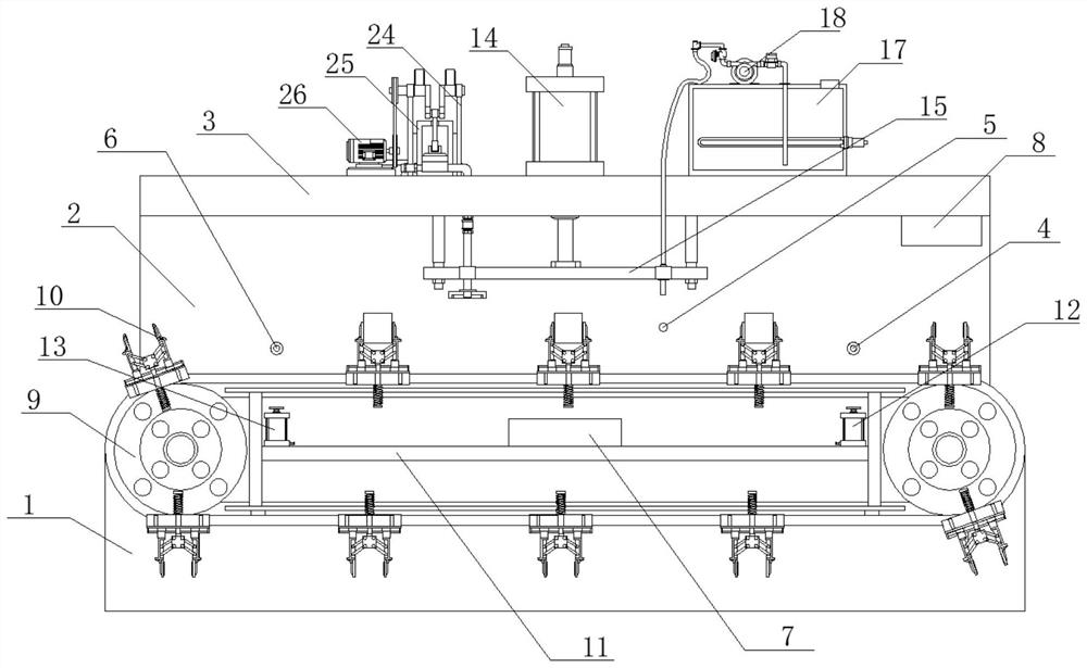
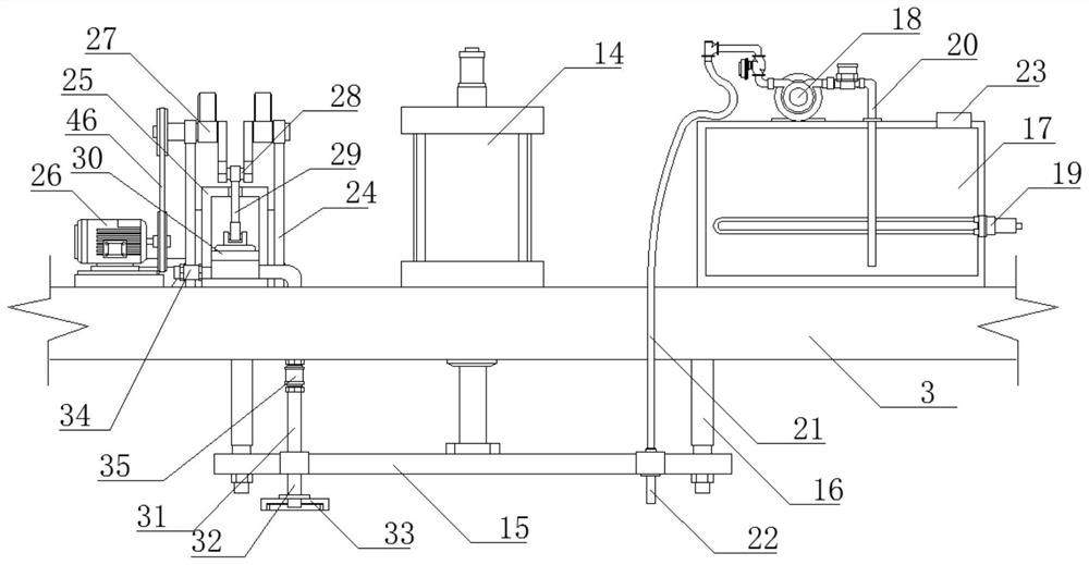
[0035]A potting device for a gradient sensor waterproof cover, comprising a fixed seat 1, the upper end of the fixed seat 1 is fixedly connected with a frame 2, the fixed seat 1 is provided with a feeding assembly, the upper end of the frame 2 is fixedly connected with a top plate 3, and the top plate 3 The lower end is provided with a lifting mechanism, and the lifting mechanism is connected to the connection end of the potting assembly and the vacuum defoaming assembly. The frame 2 is also provided with a discharging sensor 4, a potting sensor 5 and a retrieving sensor 6, and the discharging sensor 4 and The feeding sensor 6 is electrically connected to the feeding electric control box 7, the feeding electric control box 7 is connected to the feeding assembly, the potting sensor 5 is electrically connected to the potting electric control box 8, and the potting electric control box 8 is connected to the lifting mechanism and the potting assembly and vacuum defoaming components...
Embodiment 2
[0042] A potting device for a gradient sensor waterproof cover, specifically including the following operation methods:
[0043] S1. Start the machine through the feeding electric control box 7 and the potting electric control box 8;
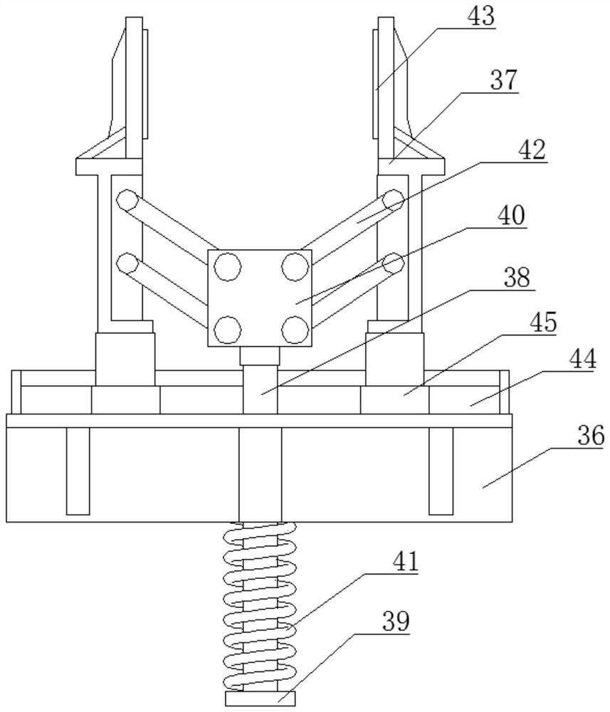
[0044] S2. The chain conveyor belt 9 drives each clamping fixture 10 to move. When a clamping fixture 10 enters the position of the discharging sensor 6, the feeding electric control box 7 receives the signal and controls the solenoid valve of the discharging cylinder 12 to open, and the discharging The piston cylinder of the air cylinder 12 pushes the limit block 39 of the clamping fixture 10, the pressure spring 41 shrinks under force, the sliding rod 38 drives the connecting piece 40 to rise, and the connecting piece 40 drives the two clamping pieces 37 through the connecting rods 29 on both sides. Open, after the workpiece is put into the workpiece by the staff or the external discharging device, the piston rod of the discharging cylinder 12...
PUM
 Abstract
Description
Claims
Application Information
 - R&D
- Intellectual Property
- Life Sciences
- Materials
- Tech Scout
- Unparalleled Data Quality
- Higher Quality Content
- 60% Fewer Hallucinations
Browse by: Latest US Patents, China's latest patents, Technical Efficacy Thesaurus, Application Domain, Technology Topic, Popular Technical Reports.
© 2025 PatSnap. All rights reserved.Legal|Privacy policy|Modern Slavery Act Transparency Statement|Sitemap|About US| Contact US: help@patsnap.com


