Real-time automatic monitoring device for salt mist sedimentation rate

An automatic monitoring and sedimentation rate technology, which is applied to the analysis of materials and instruments, can solve the problems of inability to guarantee test quality, measurement errors, large readings, etc.

Pending Publication Date: 2021-07-06
UNIV OF SCI & TECH BEIJING
View PDF5 Cites 1 Cited by
  • Summary
  • Abstract
  • Description
  • Claims
  • Application Information

AI Technical Summary

Problems solved by technology

This method is lengthy, inefficient, large in error, error-prone, and cannot realize real-time monitoring
And for the long-term salt spray test, the artificial periodic interruption of the test and the opening of the cover will affect the scientificity and rigor of the test, and it is easy to miss, and the quality of the test cannot be guaranteed.
At the same time, periodically taking out the measuring cylinder from the salt spray box will inevitably cause some irritation to the human skin and respiratory tract, which is not conducive to the health of the test personnel.
[0005] 2) Draw-out measurement method. For some small salt spray corrosion test chambers, some domestic and foreign environmental equipment manufacturers use the draw-out measurement method, using rubber hoses or plastic tubes to guide the mist collected by the collection funnel in the box. To measure and observe outside the test box, this method also requires manual participation, and the error introduced by human reading cannot be eliminated. At the same time, due to the adhesion of the hose to the fog liquid, it will cause a large reading error outside the box. For large salt Fog test equipment, this method is not applicable, because the lead-out

Method used


Image

  • Real-time automatic monitoring device for salt mist sedimentation rate

Examples


Embodiment Construction

[0042] In order to make the object, technical solution and advantages of the present invention clearer, the present invention will be further described in detail below in conjunction with the accompanying drawings and embodiments. It should be understood that the specific embodiments described here are only used to explain the present invention, not to limit the present invention.

[0043] On the contrary, the invention covers any alternatives, modifications, equivalent methods and schemes within the spirit and scope of the invention as defined by the claims. Further, in order to make the public have a better understanding of the present invention, some specific details are described in detail in the detailed description of the present invention below. The present invention can be fully understood by those skilled in the art without the description of these detailed parts.

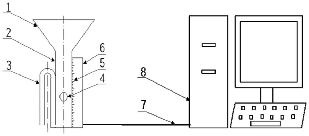
[0044] Such as figure 1 As shown, this embodiment provides a real-time automatic monitoring device fo...


PUM


Abstract

The invention discloses a real-time automatic monitoring device for a salt mist sedimentation rate, and relates to the technical field of salt mist environment simulation test measurement. The device comprises a salt solution collecting device, a salt solution emptying device, a magnetic liquid level sensor, a protective shell, a data transmission cable and an upper computer. By utilizing the siphoning effect, when the amount of a solution in the salt solution collecting device reaches a certain value, all the solution is automatically emptied, a discharge electromagnetic valve is prevented from being introduced, and the failure rate of the device is reduced. A digital circuit signal is triggered by magnetic field induction, so that contact between device parts and a salt mist environment is avoided, the service life of the device parts is prolonged, the liquid level of a collected salt solution can be monitored in real time, the signal is processed and calculated through the upper computer, a sedimentation rate curve is drawn, automatic real-time monitoring of the salt mist sedimentation rate is realized, and the device is accurate and high in timeliness. The device is simple in structural design, high in automation degree, high in safety, long in service life and high in expansibility.

Description

technical field [0001] The invention belongs to the technical field of salt spray environment simulation test measurement, and in particular relates to a real-time automatic monitoring device for salt spray settlement rate. Background technique [0002] Salt spray test is an indoor accelerated corrosion test conducted by artificially simulating salt spray environmental conditions created by salt spray environmental simulation test equipment. It is a common method for evaluating the corrosion resistance of metal materials and products and the corrosion resistance of coating materials. The salt spray sedimentation rate is an important index parameter of the salt spray environmental simulation test, which can reflect the characteristics of spray density and uniformity, and has an important impact on the test results. Almost all salt spray test standards restrict the salt spray deposition rate during the salt spray test process, and some salt spray test standards have stricter r...

Claims


Application Information

Patent Timeline
IPC IPC(8): G01N15/04
CPCG01N15/04
Inventor 金莹闫松涛宋术伟文磊王明昊
Owner UNIV OF SCI & TECH BEIJING
Why Eureka
Try Eureka