
Electron gun device and medical linear accelerator

An electron gun and accelerating tube technology, applied in the fields of electron gun devices and medical linear accelerators, can solve the problems of deviation of distance value and preset value, affecting the stability of accelerating tube of electron gun device, low repeat positioning accuracy, etc.

Pending Publication Date: 2021-07-06
SHANGHAI UNITED IMAGING HEALTHCARE
View PDF11 Cites 0 Cited by
  • Summary
  • Abstract
  • Description
  • Claims
  • Application Information

AI Technical Summary

Problems solved by technology

[0005] The object of the present invention is to provide an electron gun device and a medical linear accelerator to solve the problem of the relative gap between the electron gun cathode and the anode, the electron gun cathode and the accelerating tube cavity, or the electron gun anode and the accelerating tube cavity after the electron gun is replaced or disassembled. The accuracy of position repeat positioning is low, and there is a position deviation between the distance value and the preset value, which in turn affects the stability of the output of the electron gun device and the input of the acceleration tube.

Method used


Image

  • Electron gun device and medical linear accelerator
  • Electron gun device and medical linear accelerator
  • Electron gun device and medical linear accelerator

Examples


Embodiment 1

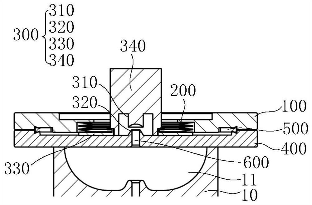
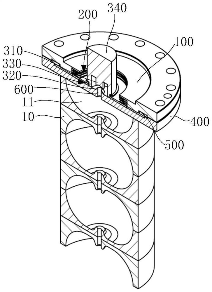
[0038] Please refer to Figure 1 to Figure 4 , figure 1 A schematic diagram of the electron gun device provided in Embodiment 1; figure 2 The schematic diagram of the electron gun device including the beam shape provided for the first embodiment; image 3 A schematic diagram of the medical linear accelerator provided in Example 1; Figure 4 A three-dimensional cross-sectional view of the medical linear accelerator provided in Embodiment 1. Figure 5 It is a schematic diagram of another electron gun device provided in Embodiment 1. Image 6 A three-dimensional cross-sectional view of another medical linear accelerator provided in Embodiment 1.

[0039] Please refer to figure 1 As shown, the electron gun device includes: a first pressing unit 100 , an elastic unit 200 , an electron gun unit 300 and a second pressing unit 400 .

[0040] Such as figure 1 and image 3 As shown, the first compression unit 100 is, for example, preferably an upper sealing flange, and the seco...

Embodiment 2

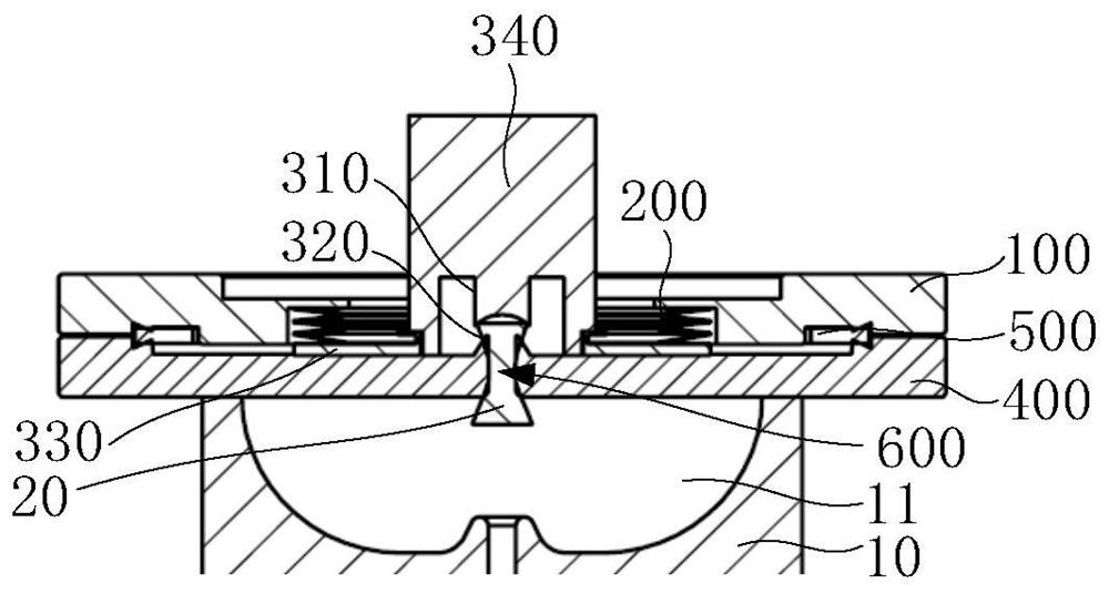
[0053] Please refer to Figure 7 to Figure 8 , Figure 7 A schematic diagram of the electron gun device provided for the second embodiment; Figure 8 A three-dimensional cross-sectional view of the medical linear accelerator provided for the second embodiment.

[0054] The same parts of the electron gun device in the second embodiment and the first embodiment will not be described, and only the differences will be described below.

[0055] Such as Figure 7 and Figure 8 As shown, the electron gun device includes: a first pressing unit 100 , an elastic unit 200 , an electron gun unit 300 and a second pressing unit 400 . The first compression unit 100 and the second compression unit 400 are connected along the axial direction of the electron gun unit 300 , and the second compression unit 400 is fixed on an acceleration tube 10 .

[0056] Such as Figure 7 As shown, the anode 320 and the cathode 310 are fixedly arranged opposite to each other along the axial direction, the...


PUM


Abstract

The invention provides an electron gun device and a medical linear accelerator. The electron gun device comprises a first pressing unit, an elastic unit, an electron gun unit and a second pressing unit. An anode is arranged on the second pressing unit, and a cathode is connected with the first pressing unit through an elastic unit and is arranged opposite to the anode; the elastic unit is arranged along the axial direction of the electron gun unit, and provides axial force for the cathode, so that the distance between the cathode and the anode is kept at a preset value; or, the anode and the cathode are fixedly and oppositely arranged in the axial direction, and the electron gun unit is connected with the first pressing unit through an elastic unit; the elastic unit is arranged in the axial direction of the electronic gun unit and provides axial force for the electronic gun unit so that the distance between the electronic gun unit and the accelerating tube can be kept at a preset value. Therefore, the stability of the output of the electron gun device and the input of the accelerating tube is ensured.

Description

technical field [0001] The invention relates to the technical field of medical equipment, in particular to an electron gun device and a medical linear accelerator. Background technique [0002] The electron gun is a device that generates, accelerates, and converges high-energy-density electron beams, which can emit electron beams with certain energy, certain beam current, speed and angle. The electron gun consists of three parts: the emitter (cathode) for generating electrons, the focusing electrode for focusing the electron beam, and the extraction electrode (anode) for accelerating electrons. When the electron gun is working, under the action of the high-voltage electric field between the anode and the cathode, the surface of the cathode heated to over 1000°C emits electrons; the focusing electrode makes the electron beams emitted by the cathode surface converge; the electron beam accelerates to the anode and forms a certain waistband. The parameters such as beam waist d...

Claims


Application Information

Patent Timeline
Patent Type & Authority Applications(China)
IPC IPC(8): H01J37/06H01J37/065H01J37/067
CPCH01J37/065H01J37/06H01J37/067
Inventor 董守增文朝廷李建波刘方沈啸彪王海堂向翔翔孙明芳李玉鹤
Owner SHANGHAI UNITED IMAGING HEALTHCARE
Learn More