
High-gain WiFi antenna and wireless communication terminal

A high-gain, antenna technology, applied in the direction of antenna, antenna support/mounting device, antenna grounding switch structure connection, etc., can solve the problems of low WiFi antenna gain and large signal attenuation

Active Publication Date: 2021-07-06
KUNSHAN RUIXIANG XUNTONG COMM TECHCO
View PDF5 Cites 0 Cited by
  • Summary
  • Abstract
  • Description
  • Claims
  • Application Information

AI Technical Summary

Problems solved by technology

[0005] The object of the present invention is to provide a high-gain WiFi antenna and wireless communication terminal, to at least solve the problems of low gain and large signal attenuation of existing WiFi antennas

Method used


Image

  • High-gain WiFi antenna and wireless communication terminal
  • High-gain WiFi antenna and wireless communication terminal

Examples


Embodiment Construction

[0021] The high-gain WiFi antenna and wireless communication terminal proposed by the present invention will be further described in detail below in conjunction with the accompanying drawings and specific embodiments. It should be noted that all the drawings are in a very simplified form and use imprecise scales, and are only used to facilitate and clearly assist the purpose of illustrating the embodiments of the present invention. In addition, the structures shown in the drawings are often a part of the actual structures. In particular, each drawing needs to display different emphases, and sometimes uses different scales.

[0022] It should be noted that “first” and “second” in the description and claims of the present invention are used to distinguish similar objects in order to describe the embodiments of the present invention, and are not used to describe a specific order or sequence order, it should be understood that the constructs so used are interchangeable under appr...


PUM


Abstract

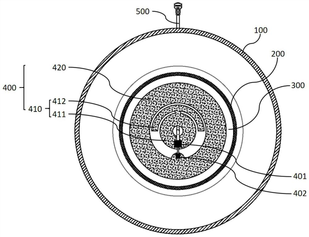
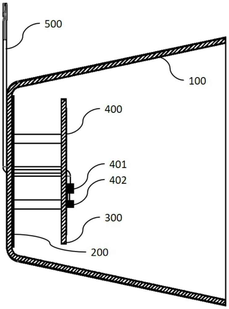
The invention provides a high-gain WiFi antenna and a wireless communication terminal. The high-gain WiFi antenna comprises a metal wall beam wave unit with a trumpet-shaped opening, a reflecting plate located at the bottom of the inner side of the metal wall beam wave unit, a PCB substrate located in the metal wall beam wave unit and an onboard antenna located on the surface of the PCB substrate. The onboard antenna comprises a first radiation unit and a second radiation unit; the first radiation unit comprises a first branch knot and a second branch knot which are communicated with each other, the first branch knot is circular, and the second branch knot is semi-circular and semi-surrounds the first branch knot; the second radiation unit is circular and surrounds the first radiation unit. Electromagnetic waves in a 2.4 GHz frequency band range are generated through the onboard antenna, and when the electromagnetic waves touch the reflecting plate and the metal wall beam wave unit, the electromagnetic waves are reflected, so that the antenna gain in a fixed direction is remarkably improved; each branch knot of the onboard antenna is in the shape of a circle (ring), so that the onboard antenna has better circular polarization, the radiation performance of the antenna is ensured, the signal attenuation is smaller, and the problems of low gain and large signal attenuation of the existing WiFi antenna are solved.

Description

technical field [0001] The invention relates to the technical field of wireless communication, in particular to a high-gain WiFi antenna and a wireless communication terminal. Background technique [0002] WiFi, also known as "mobile hotspot", now almost all smartphones, tablets and laptops support WiFi Internet access, and is the most widely used wireless network transmission technology today. [0003] Usually, the antenna for realizing the WiFi communication function includes a built-in PCB antenna, a ceramic antenna, or an external antenna by connecting the antenna extension cable through the I-PEX connector. However, most of the existing WiFi antennas are omnidirectional antennas, usually with insufficient gain in a fixed direction, the signal attenuation is too large after passing through walls, and the throughput drops significantly. [0004] With the development of wireless communication technology and people's increasing wireless communication experience, WiFi is re...

Claims


Application Information

Patent Timeline
Patent Type & Authority Applications(China)
IPC IPC(8): H01Q1/36H01Q1/22H01Q1/50H01Q15/14H01Q13/02
CPCH01Q1/36H01Q1/22H01Q1/50H01Q15/14H01Q13/02
Inventor 陈兵
Owner KUNSHAN RUIXIANG XUNTONG COMM TECHCO
Learn More