A barrel for coating and a coating machine using the barrel

A coating and barrel technology, which is applied in the direction of application, making medicines into special physical or taking forms of devices, coatings, etc., can solve the problems of single length and poor applicability, and achieves improved applicability, reasonable arrangement, Guaranteed to work properly

Active Publication Date: 2022-06-03
SHANGHAI PILOTECH INSTR & EQUIP
View PDF11 Cites 0 Cited by
  • Summary
  • Abstract
  • Description
  • Claims
  • Application Information

AI Technical Summary

Problems solved by technology

[0004] In view of the above-mentioned related technologies, when coating the material, the spray gun sprays the material upwards, and at the same time, the coating medium supply device sprays the coating medium on the blown material, and the coating medium immediately covers the surface of the material; after that, After the coating medium is dried by the hot air device, a complete coating layer is formed on the surface of the material; the inventor believes that when using the above-mentioned coating machine for coating operations, the suspension time of the material in the coating pan depends on the amount of time the material is sprayed from the spray gun. However, due to the different bonding speeds of materials and corresponding coating media, the time that materials need to be in contact with coating media is also different; when the above coating machine coats materials, the materials are in the coating pan. The length of the suspension time is relatively simple, the applicability is poor, and there is room for improvement

Method used


Image

  • A barrel for coating and a coating machine using the barrel
  • A barrel for coating and a coating machine using the barrel
  • A barrel for coating and a coating machine using the barrel

Examples


Embodiment 1

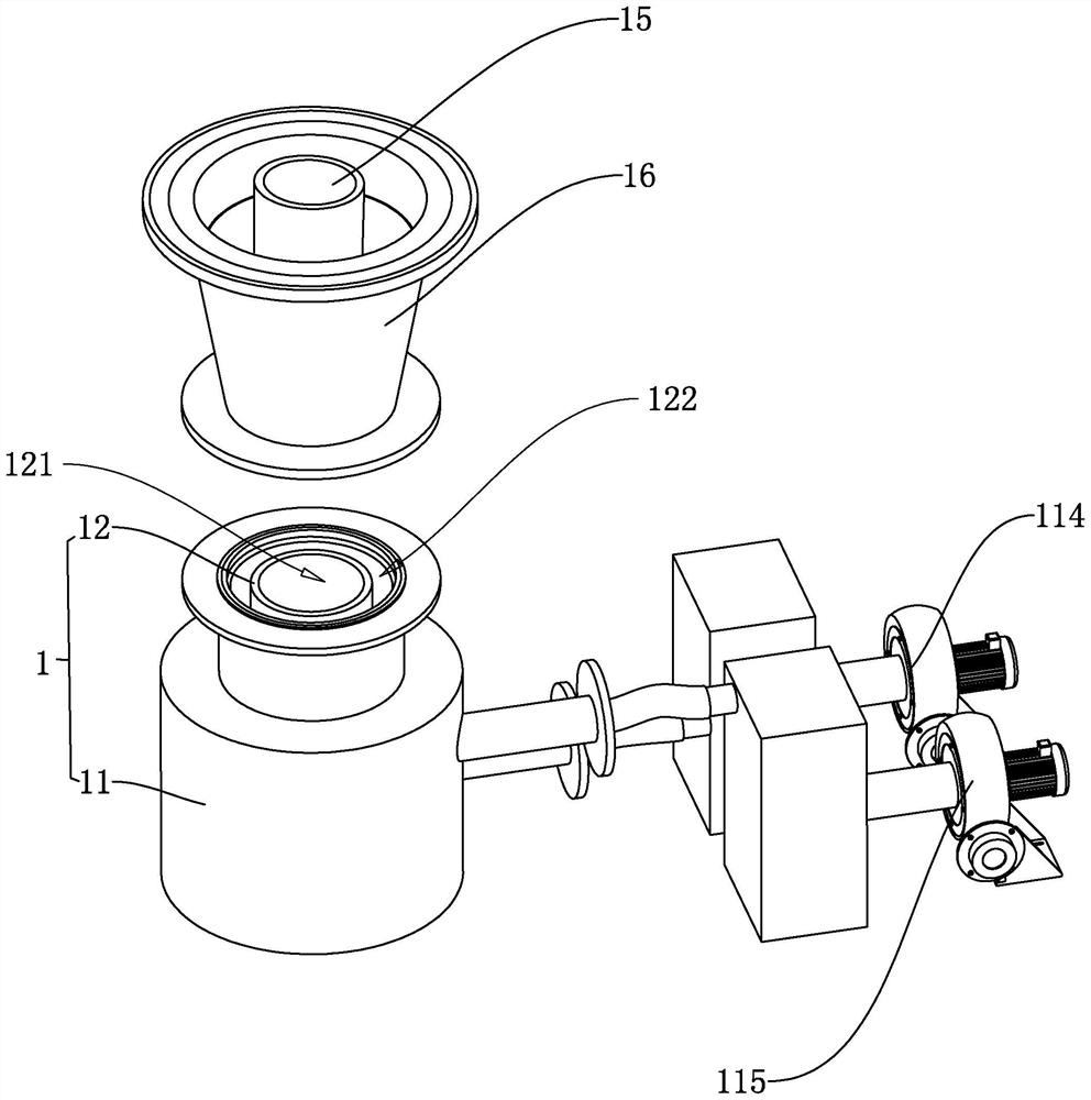
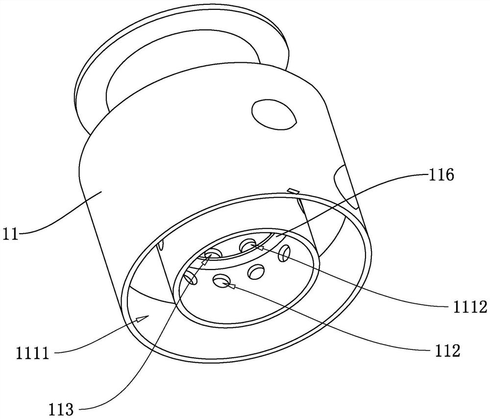
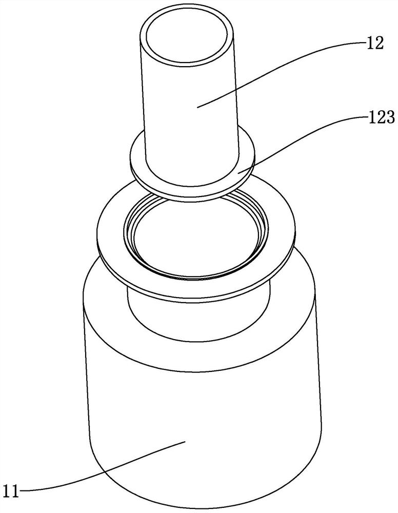
[0047] refer to figure 1 and figure 2 , a barrel body for coating, which is installed on the lower side of the feeding tray 31 of the coating machine, and is used to blow the material in the feeding tray 31 upward into the coating barrel 3, so that the material and the coating barrel 3 are blown upward. The suspended coating medium is sticky and forms a coating layer. refer to Figure 15 , including the air inlet barrel 1, the air inlet barrel 1 includes an outer cylinder 11 that communicates with the feeding tray 31, and an inner cylinder 12 embedded in the outer cylinder; A second variable frequency fan 115 is connected to the air inlet of the outer cylinder 11; at the same time, according to the difference between the ascending path and the falling path of different materials, an extension pipe 15 is communicated between the inner cylinder 12 and the feeding tray 31, and the outer A tapered tube 16 is communicated between the cylinder 11 and the material holding tray 31...

Embodiment 2

[0058] refer to Figure 7 , a coating machine, comprising the barrel in embodiment 1, the coating machine also includes a control cabinet 2, and a coating barrel 3 hinged on one side of the control cabinet 2 in the horizontal direction, the coating barrel 3 is installed on the side wall There is a feeding device 32 for spraying the coating medium; the air inlet barrel 1 is detachably fixed on the lower side of the coating barrel 3, and the air inlet barrel 1 and the coating barrel 3 are arranged in communication; the first variable frequency fan 114, the second variable frequency fan The fans 115 are installed in the control cabinet 2, and the air outlets of the first variable frequency fan 114 and the second variable frequency fan 115 are connected with ventilation pipes 17, and any ventilation pipes 17 extend out of the control cabinet 2 and are respectively connected to the corresponding first fan. Cavity 1111 and second air cavity 1112. At the same time, a heater 18 is co...


PUM


Abstract

The application discloses a barrel body for coating, which relates to the technical field of coating equipment, which includes an air inlet barrel, a first air duct and a second air duct are arranged in the air intake barrel, and the first air duct and the The second air ducts are all in communication with the material holding tray, and the air inlets of the first air duct and the second air duct are respectively connected with a first frequency conversion fan and a second frequency conversion fan. This application uses the first air channel and the first frequency conversion fan to blow the material upwards, so that the material first rises and then falls along the parabolic trajectory in the coating barrel, and uses the second air channel and the second frequency conversion fan to provide upward flow for the falling materials. Thrust, by adjusting the air output rate of the first variable frequency fan and the second variable frequency fan, the effect of adjusting the suspension time of the material in the coating barrel is achieved, which effectively improves the scope of application of the coating machine and increases its practicability.

Description

technical field [0001] The present application relates to the technical field of coating equipment, in particular to a barrel for coating and a coating machine using the barrel. Background technique [0002] In industrial production, vertical coating machines are usually used to coat Chinese and Western medicine tablets, pills and candies with sugar coating, aqueous film and organic film coating. [0003] A traditional vertical coating machine usually includes a coating pan used for coating operations, an exhaust device is connected to the upper end of the coating pan, and a coating medium supply device is arranged in the coating pan; the lower side of the coating pan is A material driving device is connected to the material driving device, and a spray gun is connected to the material driving device, and the nozzle of the spray gun faces the opening of the coating pot; the coating pot is provided with a hot air device, and the material driving device and the coating medium s...

Claims


Application Information

Patent Timeline
Patent Type & Authority Patents(China)
IPC IPC(8): A61J3/00A23G3/20B05B13/02
CPCA61J3/005A23G3/20B05B13/02Y02P70/10
Inventor 胡友华
Owner SHANGHAI PILOTECH INSTR & EQUIP
Why Eureka
Try Eureka