Numerically-controlled machine tool carriage mounting structure with good stability

A technology for CNC machine tools and installation structures, applied in feeding devices, metal processing machinery parts, measuring/indicating equipment, etc., can solve the problems of machining workpiece errors, lowering the quality of finished products, and poor feeding accuracy of machine tools, so as to prevent errors and ensure The effect of feeding accuracy and facilitating continuous operation

Inactive Publication Date: 2021-07-09
吴建和
View PDF0 Cites 1 Cited by
  • Summary
  • Abstract
  • Description
  • Claims
  • Application Information

AI Technical Summary

Problems solved by technology

[0005] Aiming at the deficiencies in the prior art, the present invention provides a stable CNC machine tool carriage installation structure, which has the advantages of timely correcting screw looseness and preventing errors in processed products, and solves the problem that the machine tool is damaged at the moment when the screw loosens. The feeding accuracy has been poor, which will lead to errors in the processed workpiece at this time and reduce the quality of the finished product.

Method used


Image

  • Numerically-controlled machine tool carriage mounting structure with good stability
  • Numerically-controlled machine tool carriage mounting structure with good stability
  • Numerically-controlled machine tool carriage mounting structure with good stability

Examples


Embodiment Construction

[0023] The following will clearly and completely describe the technical solutions in the embodiments of the present invention with reference to the accompanying drawings in the embodiments of the present invention. Obviously, the described embodiments are only some, not all, embodiments of the present invention. Based on the embodiments of the present invention, all other embodiments obtained by persons of ordinary skill in the art without making creative efforts belong to the protection scope of the present invention.

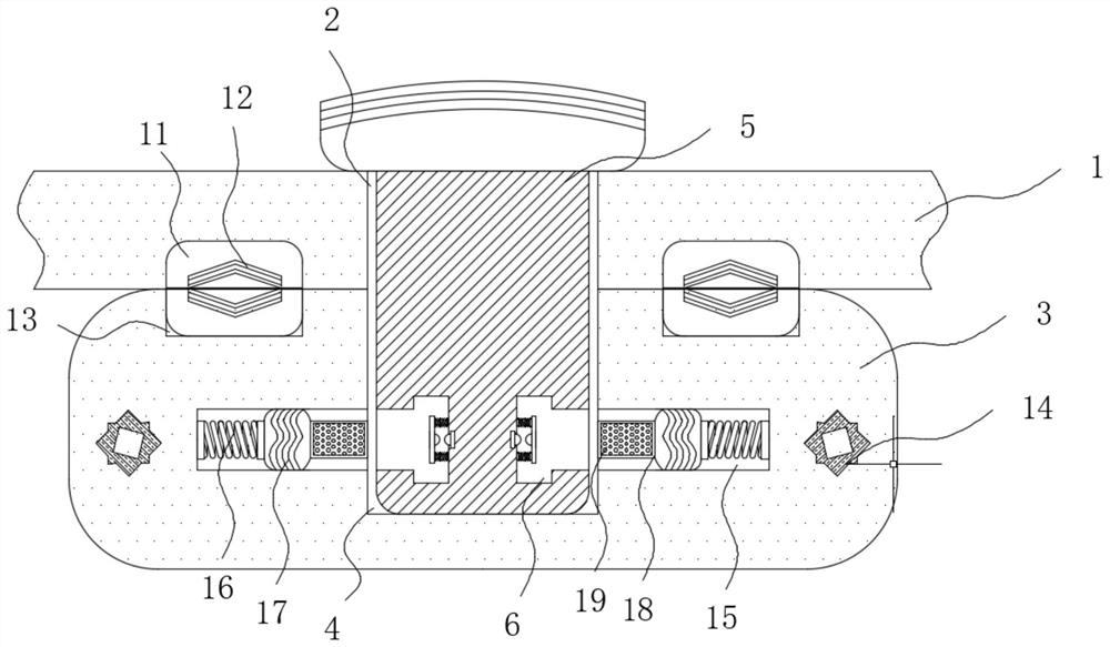
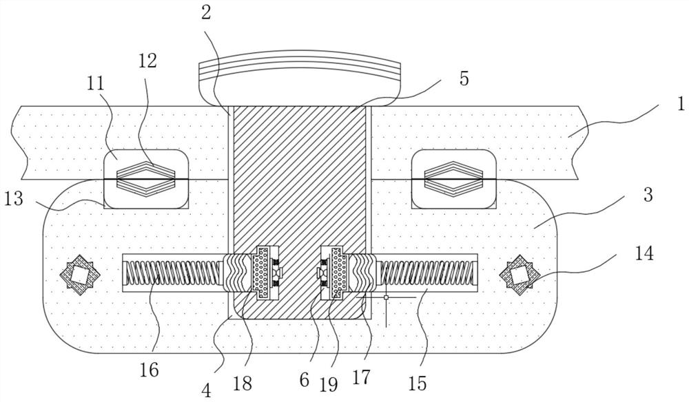
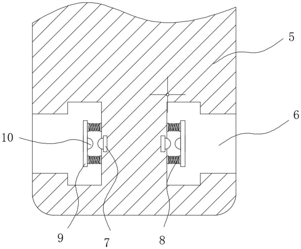
[0024] see Figure 1-4 , a stable CNC machine tool pallet installation structure, including a pallet body 1 and a screw slider 3, the pallet body 1 is provided with an installation hole 2, and the screw slider 3 is provided with a threaded hole 4 , the outer side of the tightening screw 5 is movably connected inside the threaded hole 4, the tightening screw 5 passes through the installation hole 2 and the threaded hole 4 in turn, the inner wall of the installa...


PUM


Abstract

The invention relates to the technical field of numerical control machine tools, and discloses a numerical control machine tool carriage mounting structure with good stability. The mounting structure comprises a carriage body and a screw rod sliding block, a mounting hole groove is formed in the carriage body, a threaded hole groove is formed in the screw rod sliding block, and the outer side of a tightening screw is movably connected in the threaded hole groove. A T-shaped containing groove is formed in the tightening screw, and a fixed contact is fixedly connected to the inner wall of the T-shaped containing groove. According to the numerical control machine tool carriage mounting structure with the good stability, when the tightening screw is loosened due to vibration, and a gap is formed between the carriage body and the lead screw sliding block, light leaks into the gap, an electromagnet is electrified and has magnetism, a magnet insertion shaft is pushed out along a moving long groove, accordingly, an elastic insertion shaft is pushed into the T-shaped containing groove, and an external electric field is switched on, so that the electrorheological fluid is changed into a solid state from a liquid state, and the tightening screw is stabilized in the threaded hole groove and is prevented from further loosening, so that the feeding precision is ensured, and product processing errors are prevented.

Description

technical field [0001] The invention relates to the technical field of numerical control machine tools, in particular to a stable mounting structure for a carriage of a numerical control machine tool. Background technique [0002] The machine tool carriage is the most important feeding part of the machine tool. It is responsible for carrying the processing tool assembly and realizing the feeding of the workpiece. At present, the machine tool carriage is assembled by the main body of the carriage and the screw slider. Through the screw rod slider, when the motor drives the screw rod to rotate forward and reverse, the screw rod slider moves forward or backward on the screw rod, so as to realize the feeding of the carriage body assembled with the screw rod slider. [0003] The existing machine tool carriage is connected to the carriage through the screw nut, but the machine tool will be affected by external forces during use, and sometimes there is vibration during the feeding ...

Claims


Application Information

Patent Timeline
Patent Type & Authority Applications(China)
IPC IPC(8): B23Q5/34B23Q17/00
CPCB23Q5/34B23Q17/00
Inventor 吴建和段青松熊晨
Owner 吴建和
Why Eureka
Try Eureka