Temperature-adjustable lift car structure

An adjustable and car-car technology, which is applied in air-conditioning systems, elevators in buildings, control inputs involving air characteristics, etc., can solve the problem of high cost, and achieve the effect of light structure, low power consumption, and comfortable product service

Active Publication Date: 2021-07-09
HITACHI ELEVATOR CHINA
View PDF7 Cites 0 Cited by
  • Summary
  • Abstract
  • Description
  • Claims
  • Application Information

AI Technical Summary

Problems solved by technology

[0004] The purpose of the present invention is to provide a temperature-adjustable car structure, which solves the problem of high cost in the conventional way of adjusting the temperature of the elevator car in the prior art

Method used


Image

  • Temperature-adjustable lift car structure
  • Temperature-adjustable lift car structure
  • Temperature-adjustable lift car structure

Examples


Embodiment 1

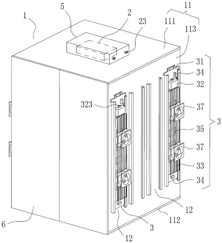
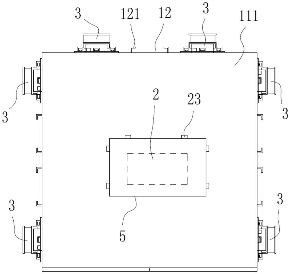
[0039] Please refer to Figure 1 to Figure 5 , this embodiment provides a temperature-adjustable car structure, including an elevator car 1, the elevator car 1 is provided with a control power supply module 2 and 6 regulators installed on the car board 11 of the elevator car Temperature device 3. The car board 11 includes a top board 111 at the top, a bottom board 112 at the bottom, and three wall boards 113 at the sides. The top of the elevator car 1 is provided with a car top electrical box 5 for installing the control power supply module 2 . Wherein, each of the three wall panels 113 is provided with two temperature regulating devices 3 . Each temperature regulating device 3 includes a heat conducting fixed plate 31 , a control unit 32 , a radiator 33 , two temperature sensing switches 34 and five serially connected semiconductor refrigerators 35 . The heat conduction fixing plate 31 is a metal plate, which may be an aluminum plate, a copper plate, an iron plate, or a st...

Embodiment 2

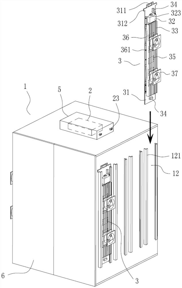
[0051] Please refer to Figure 6-9 This embodiment provides another temperature-adjustable car structure. The difference from Embodiment 1 is that the temperature regulating device 3 is rotatably mounted on the wall plate 113 of the car plate 11 in a hinged manner. Specifically, the two opposite wall panels 113 of the car plate 11 are each provided with an opening 13, the upper side of the opening 13 is provided with a loose leaf 14, and the upper end of the heat conducting fixed plate 31 rotates with the loose leaf 14. connection, the lower end of the heat conduction fixing plate 31 is provided with a first plug-in piece 313 through which a plug 314 is inserted, and the wall plate 113 of the car plate 11 is provided with a second plug-in piece for the plug-in of the plug 314 15. By hingedly connecting the heat conduction fixing plate 31 with the hinge 14 at the opening, the temperature regulating device 3 can be flipped open to the inside of the car, which is convenient for ...


PUM


Abstract

The invention discloses a temperature-adjustable lift car structure. The temperature-adjustable lift car structure comprises an elevator lift car, the elevator lift car is provided with a control power supply module and at least one temperature adjusting device, and the temperature adjusting devices can be arranged on a lift car plate of the elevator lift car or in the lift car. Each temperature adjusting device comprises a heat conduction fixing plate, a control unit, a radiator, at least one temperature sensing switch and at least one semiconductor refrigerator, wherein the control unit, the radiator, the temperature sensing switches and the semiconductor refrigerators are arranged on the heat conduction fixing plate, the semiconductor refrigerators are located between the radiator and the heat conduction fixing plate, the semiconductor refrigerators and the temperature sensing switches are electrically connected with the control unit, the control unit controls the power supply semiconductor refrigerators to be positively or reversely connected, and the control power supply module is electrically connected with the control unit. The effects of low energy consumption and temperature adjustment are achieved by arranging the temperature adjusting devices and matching with the control power supply module, the structural weight is light, installation is convenient, and the cost for achieving, using and maintaining the lift car temperature adjusting function is effectively reduced.

Description

technical field [0001] The invention relates to the technical field of elevator equipment, in particular to a temperature-adjustable car structure. Background technique [0002] With the continuous development of society, there are more and more multi-functional commercial and residential buildings. As a vertical transportation tool, elevators are widely used and become an indispensable transportation tool in people's life and work. [0003] At present, in order to realize the temperature regulation function of the elevator car, a compressor split type air conditioner is installed on the upper part of the car, and a special accompanying cable is added. Due to the weight of the air conditioner, the energy consumption of the elevator, counterweight and other use and structural costs are increased, resulting in an increase in the cost of the elevator and unnecessary waste of energy consumption during operation. Contents of the invention [0004] The purpose of the present in...

Claims


Application Information

Patent Timeline
Patent Type & Authority Applications(China)
IPC IPC(8): B66B11/02F24F5/00F24F11/88F24F11/89F24F110/10
CPCB66B11/0226B66B11/024F24F5/0042F24F11/88F24F11/89F24F2110/10
Inventor 林汪金
Owner HITACHI ELEVATOR CHINA
Why Eureka
Try Eureka