Special lifting appliance convenient to disassemble for steel structure

A steel structure and spreader technology, applied in the direction of load hanging components, transportation and packaging, etc., can solve the problems of reducing risks, and achieve the effects of reducing risks, simple operation and high safety

Active Publication Date: 2021-07-09
XINJIANG SUZHONG CONSTR ENG
View PDF15 Cites 0 Cited by
  • Summary
  • Abstract
  • Description
  • Claims
  • Application Information

AI Technical Summary

Problems solved by technology

[0004] In order to overcome the deficiency in the prior art that after the steel component is hoisted in place, the steel wire rope bound between the component lifting point and the tower crane hook needs to be released manually, the present invention provides a special lifting tool for steel structure that is easy to disassemble. The binding connection and unbinding process between the point and the hook of the lifting equipment are all completed by the staff on the ground, which avoids the risk of construction personnel climbing up and down. At the same time, the locking structure has a locking effect on the fixed bolt, forming an insurance effect, reduce the risk, so that the first pull rod will not be unhooked due to human misuse of the pull rope

Method used


Image

  • Special lifting appliance convenient to disassemble for steel structure
  • Special lifting appliance convenient to disassemble for steel structure
  • Special lifting appliance convenient to disassemble for steel structure

Examples


Embodiment 1

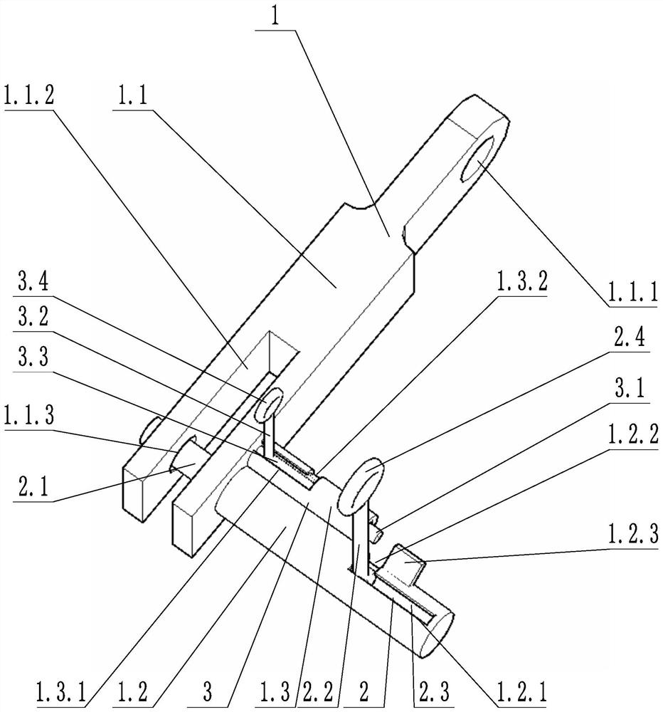
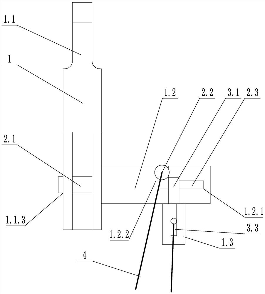
[0031] Such as image 3 As shown, a special spreader for steel structures that is easy to disassemble includes a spreader body 1, a fixed structure 2, a locking structure 3 and a pull rope 4. The spreader body 1 includes a connecting block 1.1, a first sleeve 1.2 and a second The casing 1.3, the first casing 1.2 is perpendicular to the axis of the second casing 1.3, the connecting block 1.1 is provided with a socket 1.1.3, the socket 1.1.3 passes through the connecting groove 1.1.2 transversely, the first casing 1.2 The side wall of the side wall is provided with a first slide groove 1.2.1 and a first lock groove 1.2.2 which communicate with each other.

[0032] The fixed structure 2 includes a fixed pin 2.1, a first pull rod 2.2 and a first telescopic spring 2.3. The fixed pin 2.1 is arranged in the first sleeve 1.2 and is slidably connected with the first sleeve 1.2. The fixed pin 2.1 can move along the first sleeve 1.2. One end of the fixed bolt 2.1 passes through the sock...

Embodiment 2

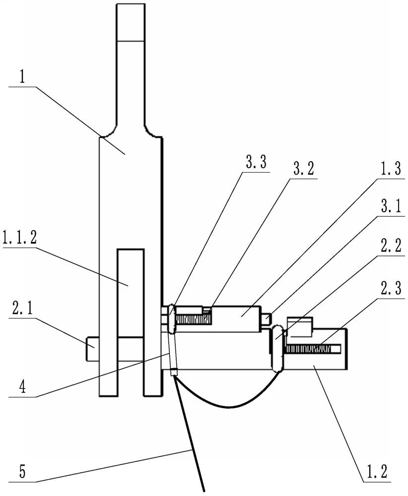
[0036] Such as figure 1 As shown, a special spreader for steel structures that is easy to disassemble includes a spreader body 1, a fixed structure 2, a locking structure 3 and a pull rope 4. The spreader body 1 includes a connecting block 1.1, a first sleeve 1.2 and a second Sleeve 1.3, connecting block 1.1 is provided with jack 1.1.3, connecting hole 1.1.1 and connecting groove 1.1.2, jack 1.1.3 passes through connecting groove 1.1.2 transversely, side wall of first bushing 1.2 There are interconnected first chute 1.2.1 and first lock groove 1.2.2; the side wall of the second casing 1.3 is provided with interconnected second chute 1.3.1 and second lock groove 1.3. 2.

[0037] The fixed structure 2 includes a fixed pin 2.1, a first pull rod 2.2 and a first telescopic spring 2.3. The fixed pin 2.1 is arranged in the first sleeve 1.2 and is slidably connected with the first sleeve 1.2. The fixed pin 2.1 can move along the first sleeve 1.2. One end of the fixed bolt 2.1 passes...

Embodiment 3

[0041] Such as figure 1 and figure 2 As shown, on the basis of Example 2, the first pull rod 2.2 and the second pull rod 3.2 are connected to the same pull rope 4; the second pull rod 3.2 is provided with an elastic stretchable part 5, and one end of the elastic stretchable part 5 is connected to the second The pull rod 3.2 is connected, and one end of the stay rope 4 is fixed to the elastic stretchable member 5 and passed through the elastic stretchable member 5 and connected with the first pull rod 2.2.

[0042] In the above technical solution, the elastic stretchable member 5 may be a stretchable spring or an elastic elastic rope or other elastic members. One end of the stay rope 4 is bound on the first pull rod 2.2, and after leaving an appropriate margin, tie a knot and then tie it on the elastic expansion member 5 on the second pull rod 3.2. The effect of the elastic telescopic member 5 is to adjust the length of the rope between the two pull rods, and give the second...


PUM


Abstract

The invention discloses a special lifting appliance convenient to disassemble for a steel structure. The special lifting appliance comprises a lifting appliance body, a fixing structure, a locking structure and a pull rope, the lifting appliance body comprises a connecting block, a first sleeve and a second sleeve, the connecting block is provided with an insertion hole, and the side wall of the first sleeve is provided with a first sliding groove and a first locking groove which communicate with each other; The fixing structure comprises a fixing bolt, a first pull rod and a first telescopic spring, the fixing bolt is slidably connected with the first sleeve, one end of the fixing bolt penetrates through the insertion hole, and the other end of the first pull rod penetrates through the first locking groove. The locking structure comprises a locking bolt and a second telescopic spring, the locking bolt is in sliding connection with the second sleeve, and one end of the locking bolt is in contact with the first pull rod. The first pull rod and the locking bolt are respectively connected with the pull rope. The special lifting appliance for the steel structure is convenient to disassemble, the risk that constructors climb up and down is avoided, and meanwhile, the locking structure has a locking effect on the fixing bolt, so that a safety effect is achieved.

Description

technical field [0001] The invention relates to the technical field of engineering construction, in particular to a special hoist for a steel structure that is easy to disassemble. Background technique [0002] In the construction of traditional steel structure housing projects, steel columns and steel plate walls are generally installed every three floors. The height of a single steel component is high, and the cross-section is mostly long. When the steel component is hoisted in place, it needs to be lifted manually The wire rope tied between the point and the tower crane hook. Since there is no safety ladder for the construction workers to go up and down vertically in this process, the construction workers mostly use the original climbing method. After connecting the safety belt on the body with the fall arrester on the hook, they step on the pegs on the steel member to go up and down the steel. Since the height of a single component is more than 9 meters, there is a risk...

Claims


Application Information

Patent Timeline
Patent Type & Authority Applications(China)
IPC IPC(8): B66C1/10
CPCB66C1/10
Inventor 顾李平曹国军白小松
Owner XINJIANG SUZHONG CONSTR ENG
Why Eureka
Try Eureka