
S-shaped spray pipe with impact-air film cooling structure and used for self-adaptive cycle engine

A film cooling and self-adaptive technology, applied in the direction of machines/engines, jet propulsion devices, etc., can solve the problems of destruction, high infrared radiation of destruction, large thermal stress of S-curved nozzles of adaptive cycle engines, etc., and achieve suppression of hot spots , Ensure aerodynamic performance, enhance the effect of infrared stealth

Active Publication Date: 2021-07-09
NORTHWESTERN POLYTECHNICAL UNIV
View PDF7 Cites 0 Cited by
  • Summary
  • Abstract
  • Description
  • Claims
  • Application Information

AI Technical Summary

Problems solved by technology

[0006] In order to avoid the deficiencies of the prior art, the present invention proposes a S-curved nozzle of an adaptive cycle engine with an impact-film cooling structure to solve the existing Technology adaptive cycle engine S-bend nozzle failure due to large thermal stress on the inside and outside of the wall, local damage caused by local thermal shift, and high infrared radiation caused by high-temperature nozzle wall and high-temperature exhaust gas

Method used


Image

  • S-shaped spray pipe with impact-air film cooling structure and used for self-adaptive cycle engine
  • S-shaped spray pipe with impact-air film cooling structure and used for self-adaptive cycle engine

Examples


Embodiment Construction

[0026]The embodiments described below by referring to the figures are exemplary and are intended to explain the present invention and should not be construed as limiting the present invention.

[0027] In describing the present invention, it should be understood that the terms "center", "longitudinal", "transverse", "length", "width", "thickness", "upper", "lower", "front", " Orientation indicated by rear, left, right, vertical, horizontal, top, bottom, inside, outside, clockwise, counterclockwise, etc. The positional relationship is based on the orientation or positional relationship shown in the drawings, which is only for the convenience of describing the present invention and simplifying the description, rather than indicating or implying that the referred device or element must have a specific orientation, be constructed and operated in a specific orientation, Therefore, it should not be construed as limiting the invention.

[0028] Such as figure 2 As shown, an S-curv...


PUM


Abstract

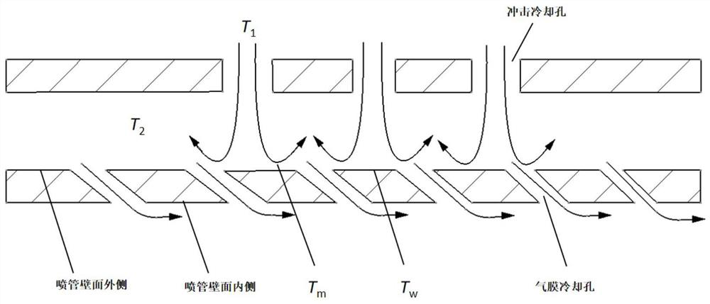
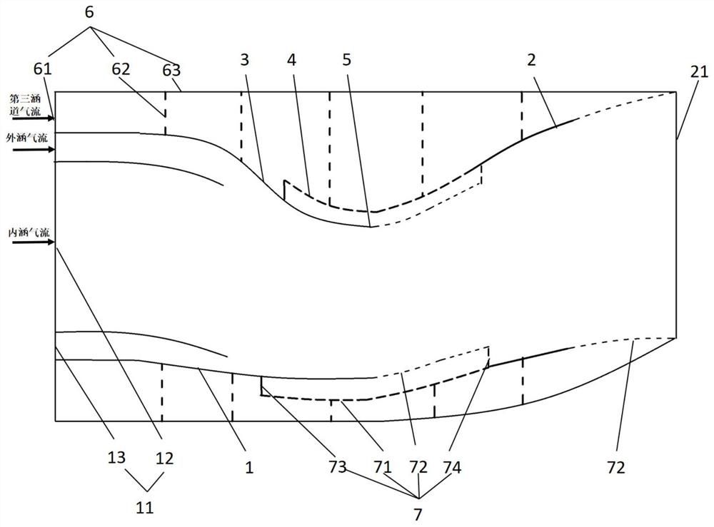
The invention discloses an S-shaped spray pipe with an impact-air film cooling structure and used for a self-adaptive cycle engine, and belongs to the field of aero-engines. The S-shaped spray pipe with the impact-air film cooling structure and used for the self-adaptive cycle engine comprises a convergence section, an expansion section and a third duct, wherein the third duct is provided with two outlets, and the first outlet is located at a throat of the spray pipe and is of the impact-air film cooling structure; the second outlet is located at an exhaust port of the spray pipe and consists of a plurality of first air film cooling holes formed in the circumferential surface of the spray pipe; the impact-air film cooling structure comprises an impact cooling hole, a second air film cooling hole, a support plate and a rectifying plate, and the outer wall surface of the spray pipe and the inner wall surface of the spray pipe are fixedly supported through the support plate and the rectifying plate; the plurality of impact cooling holes are formed in the outer wall surface of the spray pipe in the circumferential direction, so that cold airflow in the third duct penetrates through the impact cooling holes to be sprayed to the inner wall face of the spray pipe; and the plurality of second air film cooling holes are formed in the inner wall surface of the spray pipe in the circumferential direction and located in the expansion section side of the spray pipe. According to the invention, large thermal stress caused by large temperature difference between the inner side and the outer side of the wall surface of the spray pipe is prevented, the thermal stress is reduced, and the wall surface is protected.

Description

technical field [0001] The invention belongs to the field of aero-engines, and in particular relates to an S-curved nozzle of an adaptive cycle engine with an impact-film cooling structure. Background technique [0002] The variable cycle engine regulates the thermal cycle characteristics of the engine by changing the position, geometric size and shape of the internal components of the engine, so that it can take into account the advantages of low-speed and high-speed flight performance, so it will be widely used in the new generation of fighter jets. Adaptive cycle engine is the latest generation of variable cycle engine. Its biggest feature is that it has three flow channels, so it has more working modes and stronger cycle adjustment ability. At the present stage, most nozzle designs for adaptive cycle engines are for axisymmetric convergent nozzles, which can only be used for subsonic flight. In order to achieve transonic and supersonic flight, it is necessary to study t...

Claims


Application Information

Patent Timeline
IPC IPC(8): F02K1/78F02K1/82
CPCF02K1/78F02K1/822
Inventor 惠中豪史经纬周莉王占学刘永泉
Owner NORTHWESTERN POLYTECHNICAL UNIV
Learn More