Water sample collecting device for water conservancy project

A collection device and water conservancy engineering technology, applied in the direction of sampling devices, etc., can solve the problems of inability to collect water samples, deviation of sampling and detection results, etc., and achieve the effects of being suitable for popularization and use, improving accuracy, and being convenient to use

Pending Publication Date: 2021-07-09
程秋霞
View PDF0 Cites 0 Cited by
  • Summary
  • Abstract
  • Description
  • Claims
  • Application Information

AI Technical Summary

Problems solved by technology

[0004] A water sample collection device for water conservancy projects proposed by the present invention solves the problem that existing water sample collection devices for water conservancy projects cannot collect water samples at different depths, resulting in deviations in sampling and detection results

Method used


Image

  • Water sample collecting device for water conservancy project
  • Water sample collecting device for water conservancy project
  • Water sample collecting device for water conservancy project

Examples


Embodiment 1

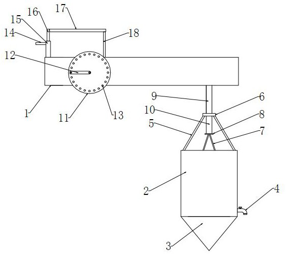
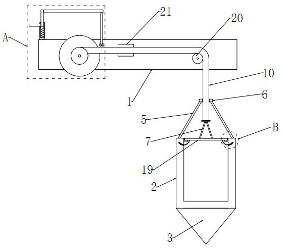
[0028] refer to figure 1 , figure 2 , Figure 5 and Image 6 , a water sample collection device for water conservancy projects, comprising an installation frame 1 and a collection bucket 2, the installation frame 1 is arranged in a U-shaped structure, and a winding rod 24 is rotatably installed between the inner walls on both sides of the installation frame 1, and the wire winding rod One end of the 24 extends to the outside of the mounting frame 1 and the handle 12 is fixedly installed, and the side of the mounting frame 1 close to the handle 12 is provided with a positioning mechanism that cooperates with it. There are two symmetrically distributed first traction ropes 9, and the ends of the two first traction ropes 9 are connected with a first movable plate 6, the first movable plate 6 is located directly above the collection bucket 2, and the second traction rope 10 is located on the two sides. Between the first traction ropes 9, two symmetrically distributed partition...

Embodiment 2

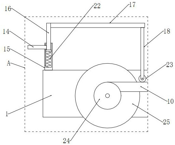
[0033] refer to Figure 1-5 , the inner wall of the collection barrel 2 is fixedly installed with two symmetrically distributed baffles 26, and the baffles 26 are located below the barrel cover 19, the bottom end of the barrel cover 19 is fixedly connected with a guide rod 27, and the inner wall of the collection barrel 2 is provided with Two symmetrically distributed guide grooves 28, and the end of the guide rod 27 is slidably installed with the inside of the guide groove 28, and is fixedly connected with an anti-separation block. The rod body of the guide rod 27 located inside the guide groove 28 is sleeved with a second A return spring 29 , one end of the second return spring 29 is connected to the anti-disconnection block, and the other end of the second return spring 29 is fixedly connected to the inner wall of the guide groove 28 .

[0034]A pressing mechanism is installed on the top of the mounting frame 1, and the pressing mechanism includes a pressing rod 14, a sleev...


PUM


Abstract

The invention discloses a water sample collection device for a water conservancy project, relates to the field of water conservancy projects, and provides the following scheme aiming at the problem that a sampling detection result has deviation due to the fact that an existing water sample collection device for the water conservancy project cannot collect water samples at different depths, the water sample collection device for the water conservancy project comprises a mounting frame and a collection barrel, a wire winding rod is rotationally mounted between the inner walls of the two sides of the mounting frame, one end of the wire winding rod extends out of the mounting frame and is fixedly provided with a handle, and a positioning mechanism matched with the mounting frame is arranged on the side, close to the handle, of the mounting frame; a second traction rope and two symmetrically-distributed first traction ropes are wound on a rod body of the winding rod, and the ends of the two first traction ropes are connected with a first movable plate. The device can sample water in water areas to be detected at different depths, improves the accuracy of water quality detection, can control the amount of sampled water, is simple to operate, and is suitable for popularization and use.

Description

technical field [0001] The invention relates to the field of water conservancy projects, in particular to a water sample collection device for water conservancy projects. Background technique [0002] Water conservancy projects refer to projects constructed to eliminate water hazards and develop and utilize water resources. According to its service objects, it is divided into flood control engineering, farmland water conservancy engineering, hydroelectric power generation engineering, waterway and port engineering, water supply and drainage engineering, environmental water conservancy engineering, sea flat reclamation engineering, etc. A water conservancy project that can serve various goals such as flood control, water supply, irrigation, and power generation at the same time is called a comprehensive utilization water conservancy project. Water conservancy projects require the construction of different types of hydraulic structures such as dams, embankments, spillways, sl...

Claims


Application Information

Patent Timeline
IPC IPC(8): G01N1/10
CPCG01N1/10
Inventor 程秋霞
Owner 程秋霞
Why Eureka
Try Eureka