Distributed receiving array channel error calibration method and system based on microwave photon stable-phase transmission link

A technology of stable phase transmission and microwave photons, applied in radio wave measurement systems, instruments, etc., can solve the problem that array calibration technology is difficult to adapt to the precise calibration of array channel errors

Active Publication Date: 2021-07-09
CHINA ELECTRONIC TECH GRP CORP NO 38 RES INST
View PDF30 Cites 4 Cited by
  • Summary
  • Abstract
  • Description
  • Claims
  • Application Information

AI Technical Summary

Problems solved by technology

[0006] The technical problem to be solved by the present invention is how the existing array calibration technology is difficult to adapt to the precise calibration requirements of distributed, large-aperture, and long-distance transmission array channel errors

Method used


Image

  • Distributed receiving array channel error calibration method and system based on microwave photon stable-phase transmission link
  • Distributed receiving array channel error calibration method and system based on microwave photon stable-phase transmission link
  • Distributed receiving array channel error calibration method and system based on microwave photon stable-phase transmission link

Examples


Embodiment Construction

[0040] In order to make the purpose, technical solutions and advantages of the embodiments of the present invention clearer, the technical solutions in the embodiments of the present invention will be clearly and completely described below in conjunction with the embodiments of the present invention. Obviously, the described embodiments are part of the present invention Examples, not all examples. Based on the embodiments of the present invention, all other embodiments obtained by persons of ordinary skill in the art without creative efforts fall within the protection scope of the present invention.

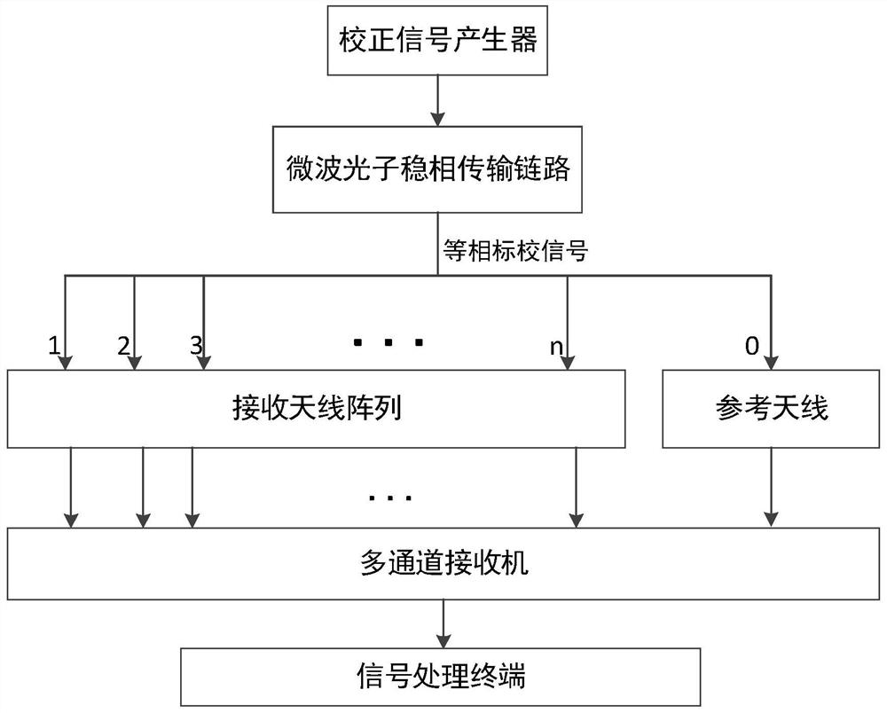
[0041] This embodiment provides a distributed receiving array channel error calibration method based on a microwave photon phase-stable transmission link, including the following steps:

[0042] Step 1. The correction signal is firstly modulated to the optical domain by a direct modulation laser, and then passed through an equal-length optical fiber to divide the signal into n li...


PUM


Abstract

The invention provides a distributed receiving array channel error calibration method based on a microwave photon stable-phase transmission link. The method comprises the following steps that firstly, a correction signal is modulated to an optical domain through a directly modulated laser, then the signal is divided into n optical carrier microwave signals through optical fibers with equal length, a photoelectric detector at each unit position of a receiving end converts the optical microwave signals into equal-phase electric signals and transmits the electric signals to a receiving antenna array so that relative stability of signal phases at all receiving end positions can be ensured; and finally (n+1) paths of equiphase calibration signals enter a receiver from all receiving channels and reference channels, and data analysis and time delay and amplitude phase estimation are carried out at a signal processing terminal. A microwave photon stable-phase transmission link is used for transmitting a calibration signal in a long distance, and it is guaranteed that the amplitude and the phase of the calibration signal fed into a front end of a distributed receiving array channel are kept consistent; and the received calibration signal is processed, and the relative amplitude, phase and time delay error among the channels are estimated.

Description

technical field [0001] The invention relates to a radar array error correction technology, in particular to a distributed receiving array channel error calibration method and system based on a microwave photon phase-stable transmission link. Background technique [0002] For a radar using a distributed receiving array system, the relative amplitude, phase, and delay errors between array channels will have a serious impact on subsequent digital beam forming (Digital Beam Forming, DBF) and other processing, so the array channel error correction become more and more important. The key to array channel error correction is to accurately estimate the relative amplitude, phase and delay errors between array channels, that is, array channel error calibration. [0003] Compared with the centralized array system, the aperture of the distributed array is generally larger, so the transmission distance of the calibration signal is very long. Under the condition of long-distance transmi...

Claims


Application Information

Patent Timeline
Patent Type & Authority Applications(China)
IPC IPC(8): G01S7/497
CPCG01S7/497
Inventor 冯威徐龙胡元奎靳学明戴泽璟周利华李科选范鹏飞张莉
Owner CHINA ELECTRONIC TECH GRP CORP NO 38 RES INST
Why Eureka
Try Eureka