Control transformer for low-consumption and energy-saving elevator

A technology for transformers and elevators, applied in the field of transformers, can solve the problems of poor heat dissipation effect, reduced service life of transformers, lack of heat dissipation devices in transformers, etc., and achieve the effect of improving service life, improving heat dissipation efficiency, and improving heat dissipation effect.

Inactive Publication Date: 2021-07-09
NANTONG MILANTE ELECTRIC
View PDF5 Cites 0 Cited by
  • Summary
  • Abstract
  • Description
  • Claims
  • Application Information

AI Technical Summary

Problems solved by technology

[0004] The purpose of the present invention is to solve the shortcomings of transformers in the prior art that lack effective heat dissipation devices and poor heat dissipation, resulting in reduced service life of transformers, and propose a low-consumption and energy-saving control transformer for elevators

Method used


Image

  • Control transformer for low-consumption and energy-saving elevator
  • Control transformer for low-consumption and energy-saving elevator
  • Control transformer for low-consumption and energy-saving elevator

Examples


Embodiment 1

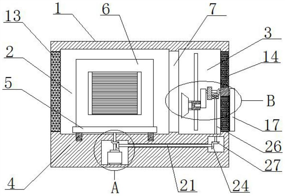
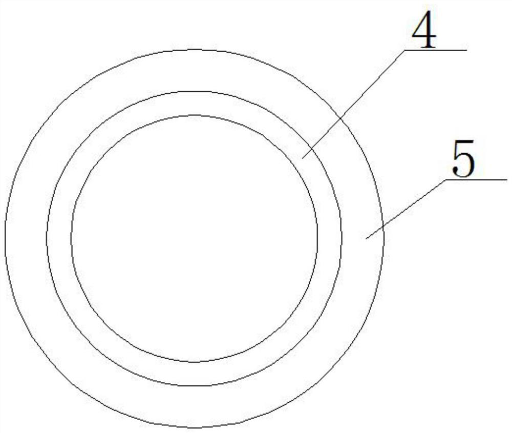
[0027] refer to Figure 1-5 , a control transformer for low-consumption and energy-saving elevators, including a housing 1 and a transformer main body 6, a first installation cavity 2 and a second installation cavity 3 are opened in the housing 1, and an annular chute is opened on the bottom inner wall of the first installation cavity 2 , a slip ring 4 is slidably installed in the annular chute, the top of the slip ring 4 is fixedly connected with a placement plate 5, the transformer main body 6 is arranged on the top of the placement plate 5, the first installation cavity 2 and the second installation cavity 3 are close to each other The same port 7 is opened on the side, and a heat dissipation mechanism is slidably installed in the second installation cavity 3. A motor cavity is opened in the housing 1, and a motor 8 is fixedly installed on the bottom inner wall of the motor cavity. Organizations cooperate.

[0028] In this embodiment, the heat dissipation mechanism include...

Embodiment 2

[0036] refer to Figure 1-5 , a control transformer for low-consumption and energy-saving elevators, including a housing 1 and a transformer main body 6, a first installation cavity 2 and a second installation cavity 3 are opened in the housing 1, and an annular chute is opened on the bottom inner wall of the first installation cavity 2 , the slip ring 4 is slidably installed in the annular chute, the top of the slip ring 4 is fixedly connected with the placement plate 5 by welding, the transformer main body 6 is arranged on the top of the placement plate 5, the first installation cavity 2 and the second installation cavity 3 are close to each other The same port 7 is opened on one side of the second installation cavity 3, and a heat dissipation mechanism is slidingly installed in the second installation cavity 3. A motor cavity is opened in the housing 1, and a motor 8 is fixed on the bottom inner wall of the motor cavity by bolts. The motor 8 is placed with the The plate 5 c...


PUM


Abstract

The invention belongs to the field of transformers, particularly relates to a control transformer for a low-consumption and energy-saving elevator, and aims to solve the problems that the service life of an existing transformer is shortened due to the fact that the existing transformer lacks an effective heat dissipation device and is poor in heat dissipation effect. The control transformer comprises a shell and a transformer body, a first mounting cavity and a second mounting cavity are formed in the shell, an annular sliding groove is formed in the inner wall of the bottom of the first mounting cavity, a sliding ring is slidably mounted in the annular sliding groove, a placement plate is fixedly connected to the top of the sliding ring, and the transformer body is arranged at the top of the placement plate. The transformer body can be subjected to larger-area and more comprehensive air blowing heat dissipation, the situation that the transformer body is covered by dust to affect heat dissipation of the transformer body is avoided, meanwhile, cleaning can be conducted on a second dustproof net plate, the situation that the second dustproof net plate is blocked to affect airflow flowing, and consequently the heat dissipation efficiency is reduced is avoided, and the service life of the transformer body is effectively prolonged.

Description

technical field [0001] The invention relates to the technical field of transformers, in particular to a control transformer for low-consumption and energy-saving elevators. Background technique [0002] Elevator refers to the permanent transportation equipment that serves several specific floors in the building, and its car runs on at least two rigid rails that are perpendicular to the horizontal plane or less than 15° from the plumb line. There are also stepped, step boards It is installed on the crawler and runs continuously, commonly known as escalator or moving walk. When the elevator is running, it needs a transformer to control it. The transformer will heat up during work, causing the temperature of the transformer to rise. If the temperature is too high, it will affect the service life and use effect of the transformer; [0003] However, the existing transformer lacks an effective heat dissipation device, and the heat dissipation effect is poor, resulting in a reduced...

Claims


Application Information

Patent Timeline
IPC IPC(8): H01F27/08H01F27/06B01D46/10B01D46/00
CPCH01F27/085H01F27/06B01D46/10B01D46/681
Inventor 黄立军吕丽云王祥根
Owner NANTONG MILANTE ELECTRIC
Why Eureka
Try Eureka