
Optimization control method suitable for UHVDC commutation failure fault recovery
A fault recovery and commutation failure technology, applied in the direction of power transmission AC network, circuit device, reducing/preventing power oscillation, etc., can solve the problems of end AC system power shortage, commutation failure, equipment damage, etc., and achieve the suppression of UHVDC The effect of system commutation failure failure recovery subsequent commutation failure, avoiding DC current control overshoot, and alleviating the degree of DC current oscillation
- Summary
- Abstract
- Description
- Claims
- Application Information
AI Technical Summary
Problems solved by technology
Method used
Image

Examples
Embodiment Construction
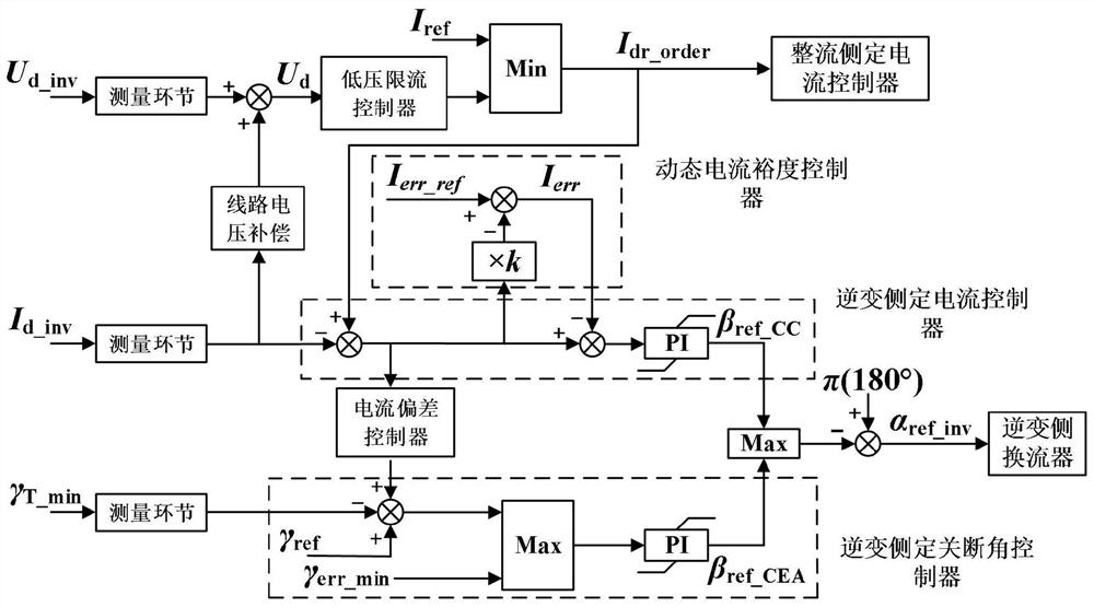
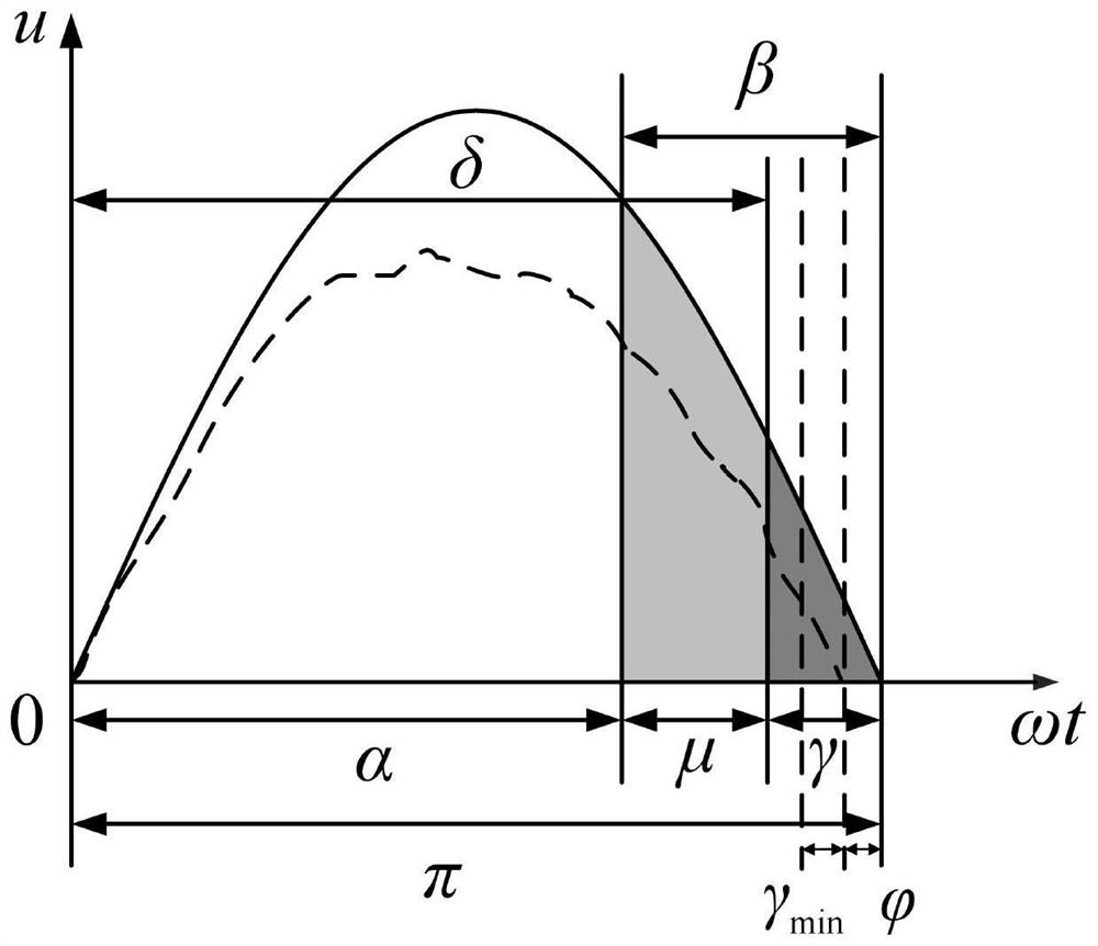
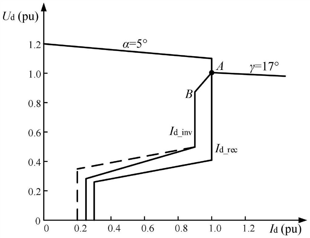
[0033] In this embodiment, the UHVDC system is composed of rectification-side AC system, rectification station, DC transmission line, inverter station, and inverter-side AC system. The hierarchical access method is adopted, and the bipolar low-end converter is connected to the 1000kV AC system. , the bipolar high-end converter is connected to the 500kV AC system. The DC controller adopts the selective controller in the CIGRE bipolar standard test model, such as figure 1 As shown, it consists of a constant current controller on the rectifier side, a low-voltage current limiting controller, a dynamic current margin controller, a current deviation controller, a constant current controller on the inverter side, and a constant turn-off angle controller on the inverter side; Inverter side DC voltage U d_inv and DC current I d_inv , the measurement link adopts the first-order inertial function, which can not only reflect the response speed of the measurement equipment, but also fil...
PUM
 Abstract
Description
Claims
Application Information