Interpolation string separation type stator coil processing device
A separate stator and processing device technology, which is applied in the field of interpolation and series separated stator coil processing devices, can solve the problems that the generator cannot generate electricity, is disorderly, and the power motor cannot rotate.
- Summary
- Abstract
- Description
- Claims
- Application Information
AI Technical Summary
Problems solved by technology
Method used
Image

Examples
Embodiment 1
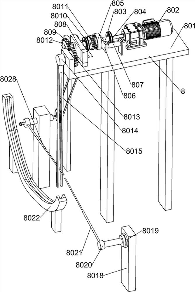
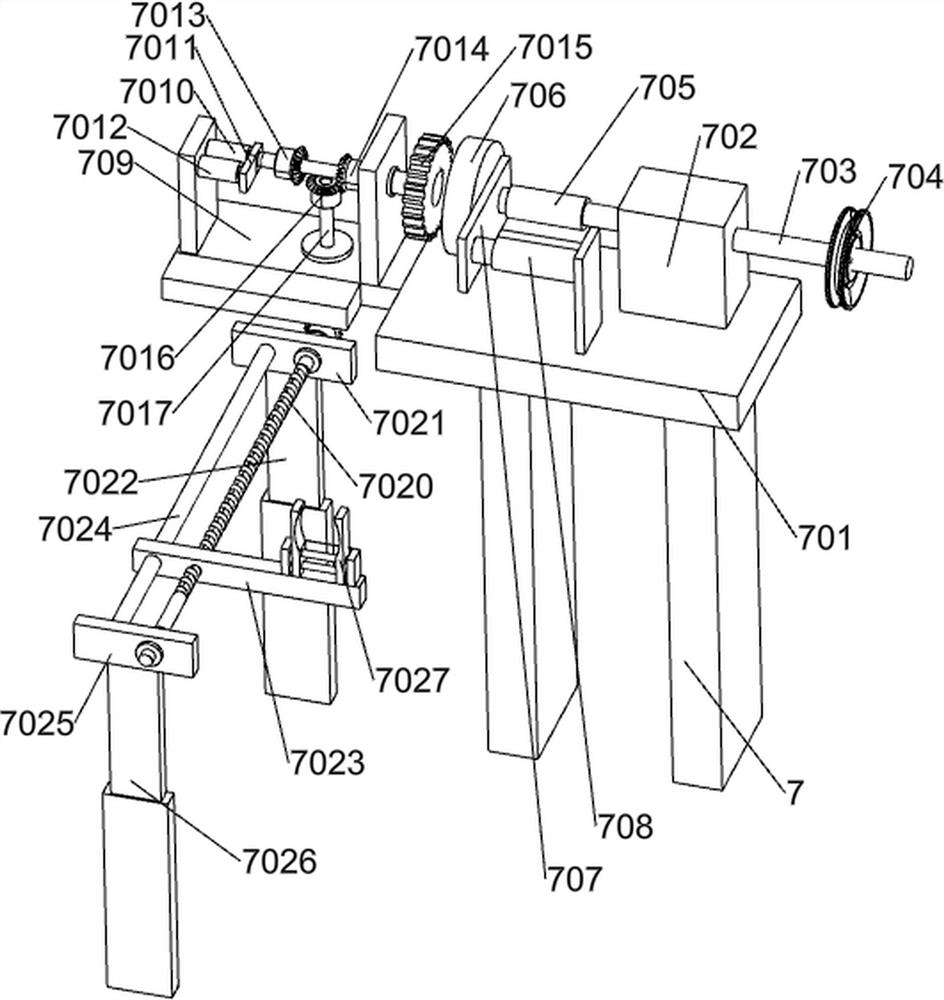
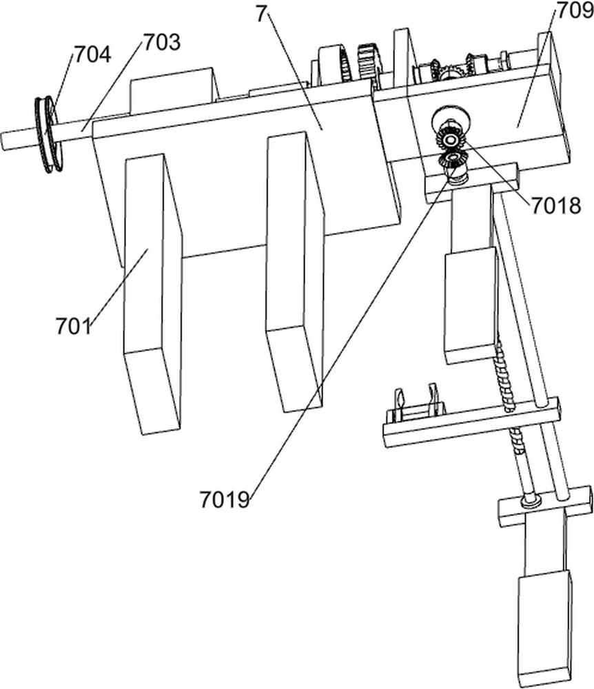
[0117] An interpolation into series separated stator coil processing device, such as Figure 1-11As shown, it includes a working machine board 1, a support stand 2, an operation support platform 3, an operation control panel 4, a turning transfer system 5, a separation system 6, an extraction system 7 and a collection system 8; the support stand 2 The upper part is welded with the working machine board 1; the lower part of the operation support table 3 is welded with the working machine board 1; the lower part of the operation control panel 4 is connected with the operation support table 3; the lower part of the turning transfer system 5 is connected with the working machine board 1; the interval is separated The bottom of the system 6 is connected with the working machine board 1; the bottom of the extraction system 7 is connected with the working machine board 1; the bottom of the lifting collection system 8 is connected with the working machine board 1, and the lifting colle...
PUM
 Abstract
Description
Claims
Application Information
 - Generate Ideas
- Intellectual Property
- Life Sciences
- Materials
- Tech Scout
- Unparalleled Data Quality
- Higher Quality Content
- 60% Fewer Hallucinations
Browse by: Latest US Patents, China's latest patents, Technical Efficacy Thesaurus, Application Domain, Technology Topic, Popular Technical Reports.
© 2025 PatSnap. All rights reserved.Legal|Privacy policy|Modern Slavery Act Transparency Statement|Sitemap|About US| Contact US: help@patsnap.com