Agricultural sprayer capable of changing spraying range based on pressure regulation
A technology of pressure regulation and spraying range, which is applied in animal husbandry, devices for catching or killing insects, applications, etc., and can solve the problems of inability to change the spraying range, large limitations, and reduced practicability
- Summary
- Abstract
- Description
- Claims
- Application Information
AI Technical Summary
Problems solved by technology
Method used
Image
Examples
Embodiment 1
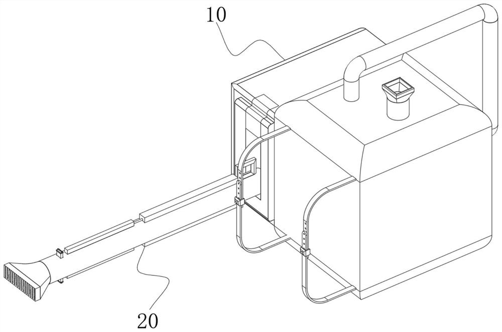
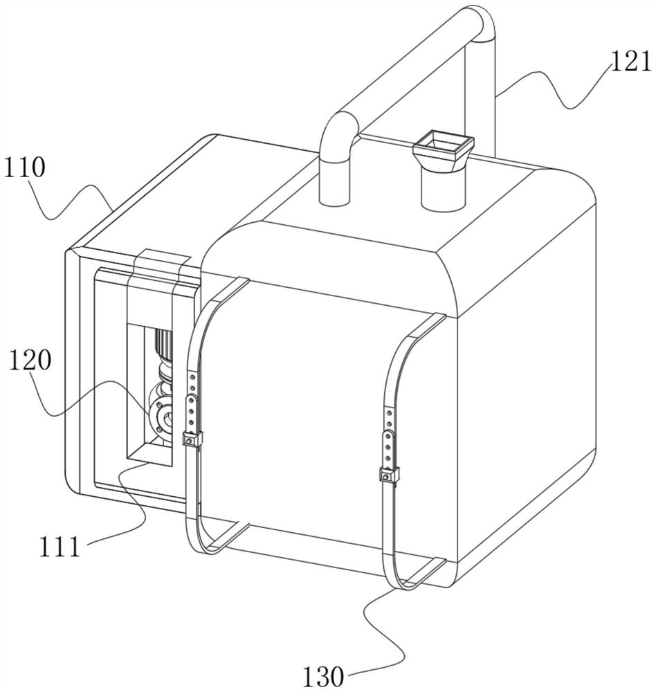
[0059] see Figure 1-Figure 11 As shown, the purpose of this embodiment is to provide an agricultural sprayer that can change the spraying range based on pressure regulation, including a spray box body 10 and a spray chamber 20 installed on the side of the spray box body 10. The side box of the spray box body 10 is provided with a side box 110, the front end of the side box 110 is provided with a card slot 111, the inside of the card slot 111 is provided with a water pump 120, the rear end of the water pump 120 is connected with a water pipe 121, and the other end of the water pipe 121 is connected to the top of the spray box 10 and extends into the spray box 10 inner ends, the spray chamber 20 at least includes:
[0060] Nozzle 210, the inner end of the nozzle 210 is a hollow structure, the inside of the nozzle 210 is provided with an inner pipe 211, the side of one end of the nozzle 210 is connected with a nozzle 212, the nozzle 212 is a funnel-shaped structure, the side of ...
Embodiment 2
[0071] see Figure 12 As shown, in order to reduce the friction between it and the inner tube 211, the extruded part 2233 has a U-shaped structure, and the bottom end of the extruded part 2233 is provided with a rolling bar 2234, and a rolling part 2235 is sleeved on the rolling bar 2234, and the rolling part 2235 has a spherical structure. The rolling friction of the rolling element 2235 is small, which can reduce the abrasion of the extruding element 2233 and the outer side of the inner tube 211 and prolong the service life of the device.
Embodiment 3
[0073] see Figure 13 As shown, in order to avoid deviation, the rolling element 2235 is in a cylindrical structure, and the inner side of the rolling element 2235 is rotationally connected with the outer side of the rolling rod 2234 . The outer side of the inner tube 211 is squeezed by the rolling member 2235 to improve its stability and avoid deviation during the rolling process, resulting in that the squeezed area of the inner tube 211 cannot achieve the effect of changing the pressure.
PUM
 Abstract
Description
Claims
Application Information
 - R&D
- Intellectual Property
- Life Sciences
- Materials
- Tech Scout
- Unparalleled Data Quality
- Higher Quality Content
- 60% Fewer Hallucinations
Browse by: Latest US Patents, China's latest patents, Technical Efficacy Thesaurus, Application Domain, Technology Topic, Popular Technical Reports.
© 2025 PatSnap. All rights reserved.Legal|Privacy policy|Modern Slavery Act Transparency Statement|Sitemap|About US| Contact US: help@patsnap.com


