Fatigue monitoring system and method fusing myoelectricity and electrocardiosignals

An electrocardiographic signal and electromyographic signal technology, which is applied in the field of biomedical electricity, can solve the problems of inability to meet the high precision of fatigue information, error-free detection, difficult and high-precision detection, etc., so as to reduce the risk of fatigue driving and improve the accuracy. , the effect of improving accuracy

Active Publication Date: 2021-07-13
NORTHWESTERN POLYTECHNICAL UNIV
View PDF5 Cites 2 Cited by
  • Summary
  • Abstract
  • Description
  • Claims
  • Application Information

AI Technical Summary

Problems solved by technology

Invention patent 201610264968.4 discloses a fatigue detection system and method based on video intelligent algorithm. The detection of the system includes judging whether the staff is on duty, judging the opening and closing of the staff's eyes and mouth, but the fusion method uses a simple weighted average calculation. In the field of traffic driving where the environment and human behavior change, it is difficult to accurately perform high-precision detection
Invention patent 201521125712.2 discloses a driver fatigue detection system based on surface electromyography technology. The fatigue detection terminal device is designed as a wearable headband. The wearable headband includes a start / stop button, surface electromyography detection electrodes, data processing and Controllers, vibration motors and wireless transmitters, but a single bioelectric signal obviously cannot meet the requirements of high-precision and error-free detection of variable fatigue information

Method used


Image

  • Fatigue monitoring system and method fusing myoelectricity and electrocardiosignals
  • Fatigue monitoring system and method fusing myoelectricity and electrocardiosignals
  • Fatigue monitoring system and method fusing myoelectricity and electrocardiosignals

Examples


specific Embodiment

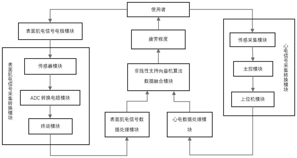
[0093] Such as figure 1 Shown is a schematic diagram of the structure of the fatigue monitoring system that fuses EMG and ECG signals,

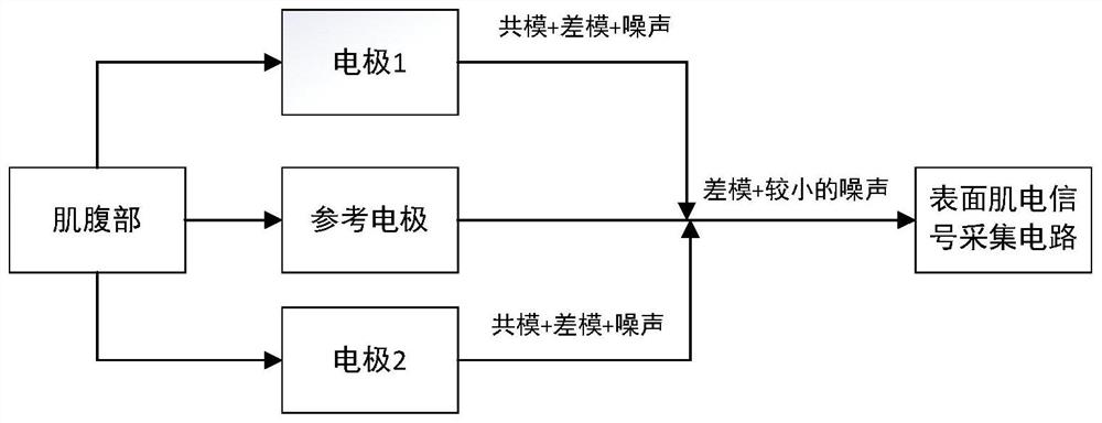
[0094] Such as figure 2 Shown is a schematic diagram of the structure of the surface electromyography signal electrode module. The substrate of the electrode sheet used in the surface electromyography signal electrode module is made of silver, and the surface is plated with silver chloride. The present invention adopts common bipolarity to measure electromyography signal, and in order to reduce noise, adds a reference electrode in the middle. The input signals detected by the two electrodes are subtracted to cancel the "common mode" component of the two, and then the "differential mode" is amplified. Because the attenuation speed of the electromyographic signal is very fast when it is transmitted in the human body, the present invention uses electrodes placed on the abdomen of the muscle. At the same time, in order to better collect EMG s...


PUM


Abstract

The invention discloses a fatigue monitoring system and method fusing myoelectricity and electrocardiosignals. The system comprises a surface electromyogram signal electrode module, a surface electromyogram signal acquisition and conversion module, a surface electromyogram signal data processing module, an electrocardiosignal acquisition and conversion module, an electrocardiosignal data processing module and a nonlinear support vector machine algorithm data fusion module. The method comprises the steps that firstly, driver surface electromyogram signals are collected, then signal amplification, filtering and A/D conversion are carried out, and then analysis is carried out to obtain characteristic parameters of the driver surface electromyogram signals; then, electrocardiosignals of a driver are collected, amplification, filtering and A/D conversion are carried out, and then characteristic parameters of the electrocardiosignals of the driver are obtained through analysis; and feature layer fusion is performed on the surface electromyographic signal feature parameters and the electrocardiographic signal feature parameters of the driver to obtain a fatigue feature vector, and the fatigue condition of the driver is judged by judging whether the feature vector conforms to fatigue features or not. The risk of fatigue driving of the driver is reduced.

Description

technical field [0001] The invention belongs to the technical field of biomedical electronics, and in particular relates to a fatigue monitoring system and method. Background technique [0002] With the development of the economy and the improvement of the quality of life of the people, the transportation industry is booming. Many newcomers are involved in the transportation industry, but their daily work and rest are not regular. When driving for a long time, the driver will inevitably get stuck sometimes, and a momentary negligence may lead to traffic accidents. Analysis of current traffic accidents shows that 75% of traffic accidents are attributed to human factors, and 21% of traffic accidents are due to fatigue driving. The dangers of fatigue driving are obvious, and the importance of how to prevent fatigue driving is self-evident. Therefore, more and more attention has been paid to the fatigue monitoring system using EMG or ECG signals. Invention patent 201610264968...

Claims


Application Information

Patent Timeline
Patent Type & Authority Applications(China)
IPC IPC(8): A61B5/318A61B5/389A61B5/18A61B5/353A61B5/366A61B5/355A61B5/363A61B5/357A61B5/00
CPCA61B5/18A61B5/165A61B5/7225A61B5/024A61B5/7203A61B2503/22
Inventor 王文东杨容霁高睿鑫胡康张子辰张培铖
Owner NORTHWESTERN POLYTECHNICAL UNIV
Why Eureka
Try Eureka