

Arc-shaped motion platform for insulator laser cleaning
A technology of arc movement and insulators, applied in the direction of cleaning methods and utensils, chemical instruments and methods, etc., to achieve the effects of ensuring focus, improving cleaning efficiency, and good applicability
- Summary
- Abstract
- Description
- Claims
- Application Information
AI Technical Summary
Problems solved by technology
Method used
Image


Examples
Embodiment 1
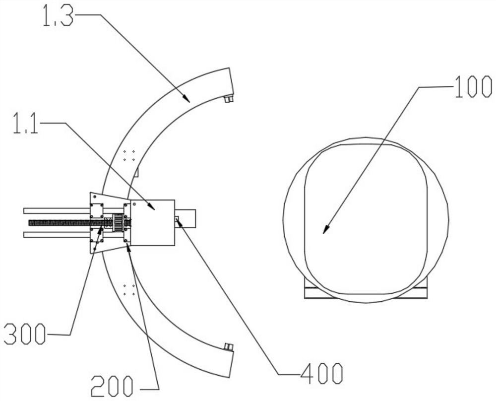
[0056] The above is Embodiment 1 of an arc-shaped motion platform for laser cleaning of insulators provided by the embodiment of the present application. The following is Embodiment 2 of an arc-shaped motion platform for laser cleaning of insulators provided by the embodiment of the application. For details, please refer to Figure 1 to Figure 4 .
[0057] Based on the technical solution of the first embodiment above:
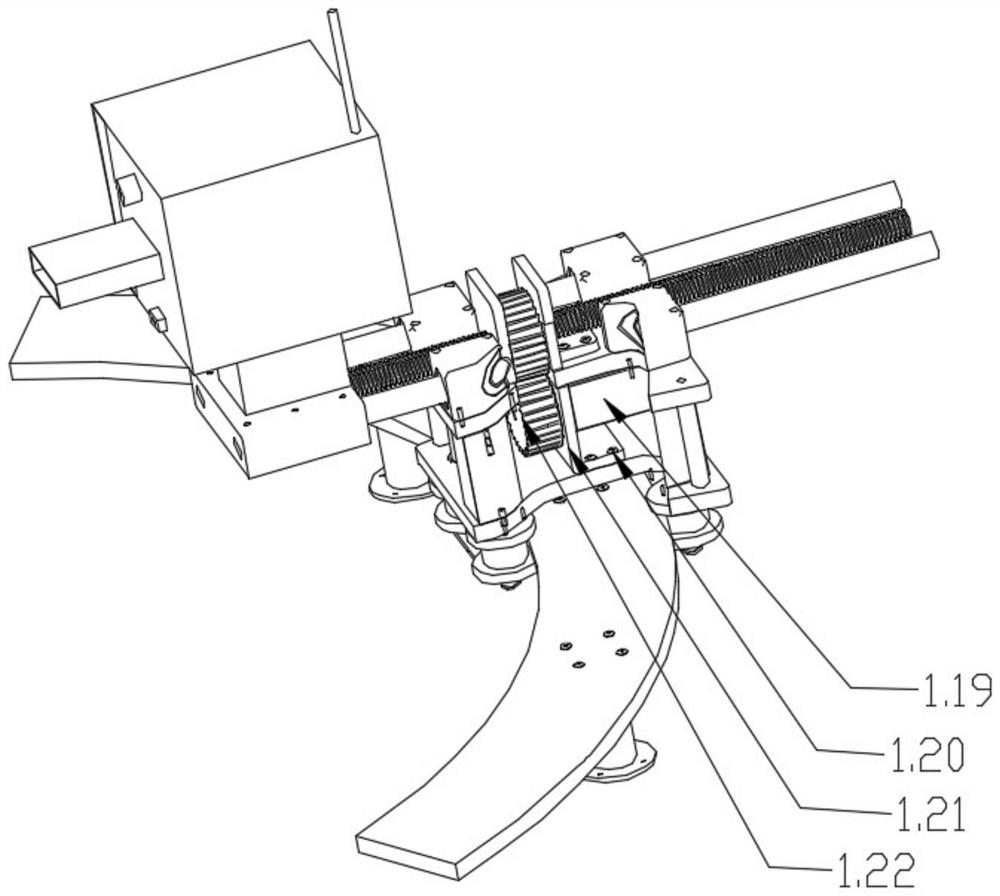
[0058] Further, in terms of the structural composition of the first moving device 200, it may include a sliding seat 1.9 and a friction wheel 1.24 mechanism. The sliding seat 1.9 slides with the arc track 1.3 through the friction wheel 1.24 mechanism; the friction wheel 1.24 mechanism is installed on the sliding seat 1.9.
[0059] Specifically, the friction wheel 1.24 mechanism may include a plurality of friction wheel sets and a first drive motor 1.10. A plurality of friction wheel sets are pivotally fixed to the bottom of the sliding seat 1.9, and are distr...
PUM
 Abstract
Description
Claims
Application Information