Forging burr removing device for high-end equipment manufacturing

A technology for equipment and forgings, applied in the field of forging burr removal equipment for high-end equipment manufacturing, can solve the problems of time-consuming, labor-intensive, easy to make people tired, etc., and achieve the effect of improving quality

Pending Publication Date: 2021-07-13
田利燕
0 Cites 0 Cited by

AI-Extracted Technical Summary

Problems solved by technology

[0004] In order to overcome the shortcomings that manual operation is not only time-consuming and labor-intensive, but also easy to make people tired, the technic...

Abstract

The invention relates to a removing device, and particularly relates to a forging burr removing device for high-end equipment manufacturing. The forging burr removing device for high-end equipment manufacturing can achieve automatic cutting and feeding. According to the technical scheme, the forging burr removing device for high-end equipment manufacturing comprises a bottom plate, frames, a placing mechanism and a stamping mechanism, wherein the two frames are connected to one side of the bottom plate; the placing mechanism is arranged on one side of the bottom plate; and the stamping mechanism is connected between the frames. Through cooperation of a rotating device, the placing mechanism and the stamping mechanism, the effects of conveying materials at intervals and removing burrs of the materials at intervals can be achieved, manual operation is not needed, and time and labor are saved.

Application Domain

Metal-working feeding devicesPositioning devices +1

Technology Topic

Manufacturing engineeringManual handling +3

Image

  • Forging burr removing device for high-end equipment manufacturing
  • Forging burr removing device for high-end equipment manufacturing
  • Forging burr removing device for high-end equipment manufacturing

Examples

  • Experimental program(2)

Example Embodiment

[0068] Example 1
[0069] A high-end equipment manufacturing forging wool removal equipment, such as Figure 1-3 As shown, there is a bottom plate 1, a shelf 2, a placed mechanism 3, and a stamping mechanism 4, and the front and rear side of the bottom plate 1 is connected to the shelf 2, and the bottom plate 1 is provided with a placed mechanism 3, and a stamping mechanism is connected between the shelf 2. 4.
[0070] The placement mechanism 3 includes a main frame 31, a first rotating shaft 32, a fixing plate 33, a placing panel 34, a second rotating shaft 35, and a six-side roller 36, and the bottom plate 1 is provided with the main frame 31, and the upper left and right sides of the main frame 31 are all. The rotation is connected to the first axis 32, and the front and rear sides of the main frame 31 are connected to the fixing plate 33, the fixing plate 33 and the first spindle 32 rotary connection, the first spindle 32 is connected to the six mite roller 36, the six mits roller The 36 is uniformly wrapped around the placing panel 34, and a second axis 35 is rotated between the placing panel 34.
[0071]The stamping mechanism 4 includes a stamper 41, a first rail 42, a pressure plate 43, a first guide post 44, a spindle 45, a punch 46, a mounting plate 47, a cylinder 48, and a cylinder 49, and a stamper 41 is connected between the shelf 2. The first rail 42 is provided on the upper right side of the upper right side of the punching frame 41, and the first rail 42 is slidably connected to the pressure plate 43, and the block 43 is slidably connected to the first guide post 44, and the mounting plate 47 is provided on the upper right side of the punching frame 41. The first guide post 44 is connected to the mounting plate 47, and the cylinder 49 is provided at the bottom of the mounting plate 47, and the cylinder 49 is provided with a cylinder 48, and the top portion of the cylinder 48 is connected, and the pressure plate 43 is provided with a spindle 45 at the bottom right side. The spindle 45 is slidable with the mounting plate 47, and a punch 46 is provided at the bottom of the main shaft 45.
[0072] When people need to be cleared to the forged blast edge, the material is placed on the placement panel 34, rotating the first rotating shaft 32 and the flap 36 and the placement panel 34 are rotated, so that the material is transferred to the left, when the material moves to the punch At the bottom of 46, the control cylinder 48 shortens the pressure plate 43, the main shaft 45, and the punch 46 move downward, so that the punch 46 is cleared, after completion, the control cylinder 48 elongates the pressure plate 43, the main shaft 45 and the punch 46 Move reset.

Example Embodiment

[0073] Example 2
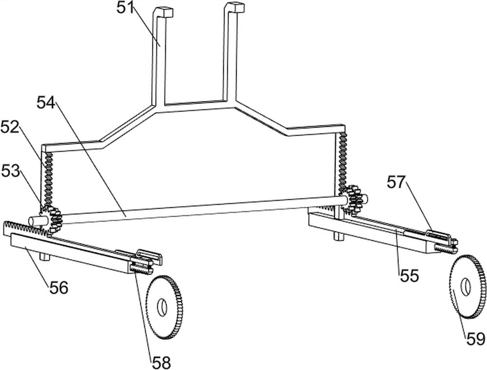
[0074] On the basis of Example 1, such as Figure 4-7 As shown, there is a rotating device 5, the rotating device 5 includes a first push rod 51, a first rack 52, a gear set 53, a rotary rod 54, a second rack 55, a slot 56, a ladder 57, a rat The rack 58 and the ratchet die 59 are connected between the front and rear sides of the pressure plate 43, and the first rack 52 is connected to the bottom front and rear sides of the first push rod 51, and the central rotation of the punching frame 41 is connected. The gear set 53 is connected to the front and rear sides of the rotor 54, and the gear set 53 consists of two gears, and the two gears are respectively provided with the front and rear sides of the rotary rod 54, and the gear set 53 and the first rack 52 mesh. The groove 56 is connected to the front and rear side of the shelf 2, and the slot 56 is slidably connected to the slot 55, the second rack 55, and the gear set 53 mesh, the second rack 55 is provided with a ladder. Block 57, both the diamonds 57 each have a ratchet 59 in front and rear sides of the first spindle 32 on the left side.
[0075] The pressure plate 43 moves downward moves the first pusher 51 and the first rack 52 downward moves downward, drive the gear set 53 and the rotary rod 54 to rotate, so that the second rack 55, the ladder 57, and the rattoper strip 58 move to the right, At this time, the ratchet 59 cannot rotate, and the pressure plate 43 moves upwardly to move the first pusher 51 and the first rack 52 upward move, drive the gear set 53 and the guard 54 to reverse, drive the second rack 55, ladder 57 and The rattybus strip 58 is reset to the left such that the ratchet 59 and the first shaft 32 are rotated, and the material is transferred to the left.
[0076] It also includes a clamping mechanism 6, a clamping mechanism 6 including a second pusher 61, a guide 62, a second guide post 63, a first spring 64, a retaining ring 65, and a clamping panel 66, and on both sides of the placement panel 34. Both are connected to the clamping panel 66, and the outer side of the clamping panel 66 is connected to the clamping panel 62, the guide frame 62 and the hierarchy panel 66 are slidably connected between the second guide post 63, the second guide post 63 Both of the second pusher 61, both sides of the second guide post 63 are provided with a retaining ring 65, and a first spring 64 is provided between the retaining ring 65 and the clamping panel 66 in the same side.
[0077] One can place the material between the clamping panel 66, the placing panel 34 rotates the guide guide 62 and the upper member to rotate, when the guide frame 62 and the upper member move to the left side of the fixing plate 33, make the second push rod The 61 and the second guide post 63 move the material to the inner side such that the first spring 64 is compressed, and when the guide frame 62 and the upper member moved to the left side away from the fixed plate 33, driven by the first spring 64 The second pusher 61 and the second guide post 63 are reset to the outside.
[0078] Also included, the laminating device 7 includes a fixed block 71, a limit post 72, a third guide post 73, a second spring 74, a lever 75, a block 76, and a chuck 77, and the left side. The chuck 77 is connected to the front and rear sides of the rotary shaft 32, and the fixed block 71 is provided on the left side of the fixing plate 33, and there are two limit column 72 at the top of the fixing block 71, and there are two thirds in the fixed block 71. The guide post 73, both sliding between the two third guide posts 73, and two second spring 74 is provided between the rod 75 and the fixed block 71 of the rod 75 and the reed 75, and the rod 75 is provided. There is a card block 76, the card block 76 and the chuck 77 card.
[0079] When the ladder 57 is in contact with the rod 75 to the right movement, the rip block 75 and the block 76 move upward, so that the block 76 and the chuck 77 are separated, the second spring 74 is compressed, and when the ladder 57 moves to the right When the rod 75 is separated, under the action of the second spring 74, the ripper 75 and the block 76 are moved downward, so that the colloidal block 76 and the chuck 77 are tacited, which in turn makes the material are fixed, and the material is carried out. When the ladder 57 is moved to the left move to the left move, the lever 75 and the block 76 are moved upward, so that the block 76 and the chuck 77 are separated, the second spring 74 is compressed, when the ladder 57 When the left move is separated from the lever 75, under the action of the second spring 74, the lever 75 and the block 76 are reset downward, so that the block 76 and the chuck 77 are tacited.
[0080] Also included include anti-retreating mechanism 8, the anti-retreating mechanism 8 includes a wedge block 81, a third spring 82, a fourth guide post 83, and a positioning block 84, and the fixed plate 33 is provided with a positioning block 84, and the positioning block 84 is Sliding is provided with the fourth guide post 83, and the fourth guide post 83 is provided with a wedge block 81, and the wedge block 81 and the locating block 84 of the same side are provided with a third spring 82.
[0081] When the ratchet 59 is rotated counterclockwise, under the action of the third spring 82, the wedge block 81 and the fourth guide post 83 can be moved constantly, and the ratchet gear 59 can be prevented from rotating clockwise.

PUM

no PUM

Description & Claims & Application Information

We can also present the details of the Description, Claims and Application information to help users get a comprehensive understanding of the technical details of the patent, such as background art, summary of invention, brief description of drawings, description of embodiments, and other original content. On the other hand, users can also determine the specific scope of protection of the technology through the list of claims; as well as understand the changes in the life cycle of the technology with the presentation of the patent timeline. Login to view more.

Similar technology patents

Data generation method and system

ActiveCN103186639AImprove entry efficiencyquality improvement
Owner:TENCENT TECH (BEIJING) CO LTD

Device for performing surface treatment on pole piece of lithium battery

InactiveCN102151665Aquality improvementReduce short circuit rate
Owner:JIANGSU YINGTAI ELECTRONICS

Cloth clipping and ironing integration device for garment production and processing

ActiveCN108179617AGood for collectionquality improvement
Owner:淮北新兴皇苑制衣有限公司

Jujube tree grafting method

InactiveCN103070025Aprevent dehydrationquality improvement
Owner:XINJIANG ACADEMY OF AGRI & RECLAMATION SCI

Classification and recommendation of technical efficacy words

Why Eureka
Try Eureka