
Battery management system

A battery management system and battery pack technology, applied in battery/fuel cell control devices, electric vehicles, vehicle energy storage, etc., can solve problems such as large amount of calculation, increased management complexity of multi-battery battery packs, and many errors.

Pending Publication Date: 2021-07-13
SHENZHEN AUTEL INTELLIGENT AVIATION TECH CO LTD
View PDF0 Cites 3 Cited by
  • Summary
  • Abstract
  • Description
  • Claims
  • Application Information

AI Technical Summary

Problems solved by technology

[0004] However, in the existing management technology, each battery in the battery pack is not considered as a whole. Individual control requires a large amount of calculation and many errors, which increases the complexity of multi-battery battery pack management, and it is difficult to achieve flexible and high-precision battery management

Method used


Image

  • Battery management system
  • Battery management system
  • Battery management system

Examples


Embodiment 1

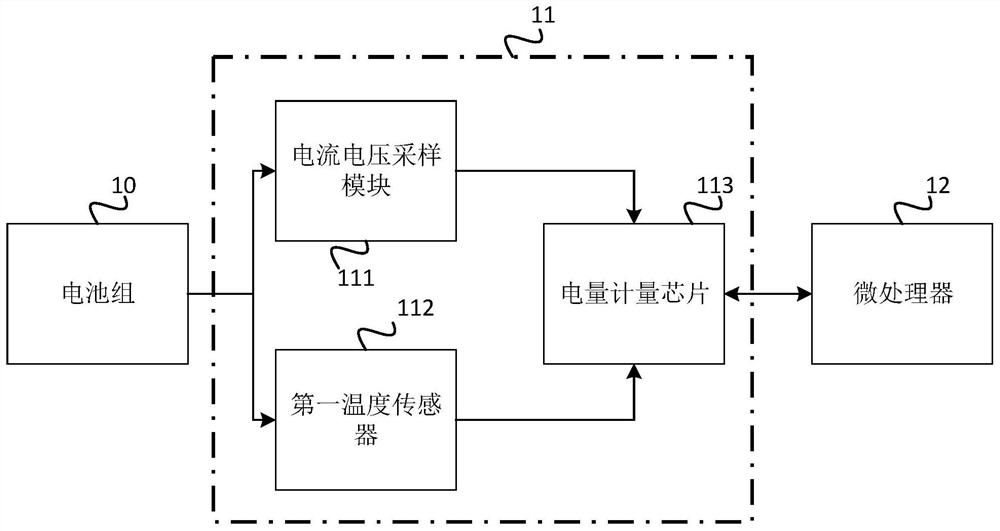
[0060] figure 1 A schematic structural diagram of a battery management system provided in Embodiment 1 of the present invention. The battery power of the battery pack is determined by the power metering device, and then the microprocessor generates a control signal according to the battery power to realize charge and discharge management of the battery pack. Such as figure 1 As shown, the battery management system includes: a battery pack 10, a power metering device 11 and a microprocessor 12, wherein:

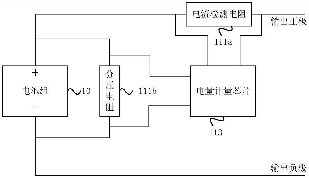
[0061] The power metering device 11 is connected to the battery pack 10 and the microprocessor 12 respectively, and is used to detect the voltage, current and temperature information of the battery pack 10 , determine the battery power of the battery pack 10 , and transmit the battery power to the microprocessor 12 .

[0062] The microprocessor 12 is configured to generate a first control signal for battery management according to the battery power.

[0063] The battery pack...

Embodiment 2

[0088] Figure 4 It is a schematic structural diagram of a battery management system provided by Embodiment 2 of the present invention. The technical solution of this embodiment is further refined on the basis of the above-mentioned technical solutions. The battery management system also includes an analog front-end device 13 and a battery pack equalization circuit 14 , reset chip 15, main circuit switch 16 and pre-charge and discharge module 17.

[0089] The analog front-end device 13 is connected with the battery pack 10 and the microprocessor 12 respectively, and is used to detect the voltage and current of each battery 101 in the battery pack 10 and the highest temperature in the battery pack 10, and generate The second control signal is used for battery management, and transmits each voltage, each current and the highest temperature to the microprocessor 12 .

[0090] The microprocessor 12 is also used to generate a third control signal for battery management according t...


PUM


Abstract

The embodiment of the invention discloses a battery management system, which comprises a battery pack, an electric quantity metering device and a microprocessor. The electric quantity metering device is respectively connected with the battery pack and the microprocessor and is used for detecting voltage, current and temperature information of the battery pack, determining the battery electric quantity of the battery pack and transmitting the battery electric quantity to the microprocessor; the microprocessor is used for generating a first control signal for battery management according to the electric quantity of the battery; and the battery pack at least comprises two serially connected batteries, is also connected with the microprocessor and is used for supplying power to the electric quantity metering device and the microprocessor. According to the technical scheme of the embodiment of the invention, the battery pack is used as a whole to calculate the electric quantity of the batteries, the electric quantity calculation precision is improved, high-precision management of the multi-battery battery pack is realized, the battery management flexibility is improved, and the information processing complexity of the microprocessor is reduced.

Description

technical field [0001] Embodiments of the present invention relate to the technical field of battery management, and in particular, to a battery management system. Background technique [0002] With the gradual rise of agricultural drones, the demand for power of drones is also increasing day by day. The increase in power means an increase in the number of batteries in the battery pack, and due to limitations in technology and product structure, there are not many multi-battery management solutions for drones at present. [0003] At present, for the management of the battery pack formed by connecting multiple batteries in the UAV, each battery in the battery pack is often managed independently through the UAV microprocessor to obtain information such as current, voltage, and temperature corresponding to each battery, and then determine each battery. Battery power and adjust the charging and discharging of different batteries. [0004] However, in the existing management te...

Claims


Application Information

Patent Timeline
IPC IPC(8): B60L58/12B60L58/18
CPCB60L58/12B60L58/18B60L2200/10Y02T10/70
Inventor 秦威
Owner SHENZHEN AUTEL INTELLIGENT AVIATION TECH CO LTD
Learn More