Supercharge Your Innovation With Domain-Expert AI Agents!

Feed packaging equipment

A feed and equipment technology, applied in the field of feed packaging equipment, can solve the problems of wasting human and material resources, and the pellets cannot be packaged, and achieve the effect of reducing operability

Inactive Publication Date: 2021-07-13
方瑞喜
View PDF0 Cites 0 Cited by
  • Summary
  • Abstract
  • Description
  • Claims
  • Application Information

AI Technical Summary

Problems solved by technology

[0002] When processing feed pellets, the processed pellets cannot be packaged, and secondary manual packaging is required, which wastes manpower and material resources

Method used


Image

  • Feed packaging equipment
  • Feed packaging equipment
  • Feed packaging equipment

Examples


specific Embodiment approach 1

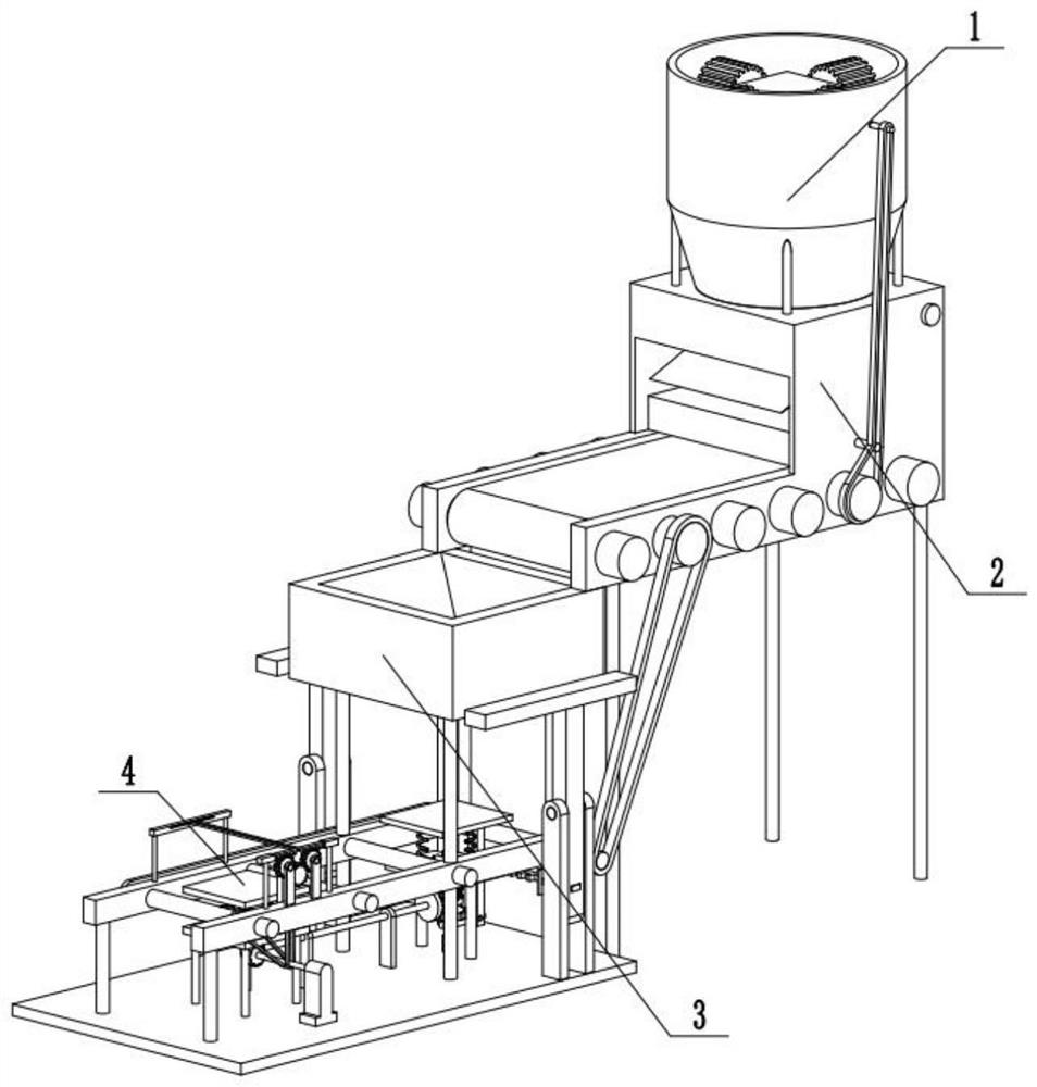
[0031] Combine below Figure 1-14 Describe this embodiment, a feed packaging equipment, including a feed assembly 1, a transmission assembly 2, a packaging assembly 3, and a sealing assembly 4, the feed assembly 1 is connected to the transmission assembly 2, and the transmission assembly 2 is connected to the sealing assembly 4, Packing assembly 3 is connected with sealing assembly 4.

specific Embodiment approach 2

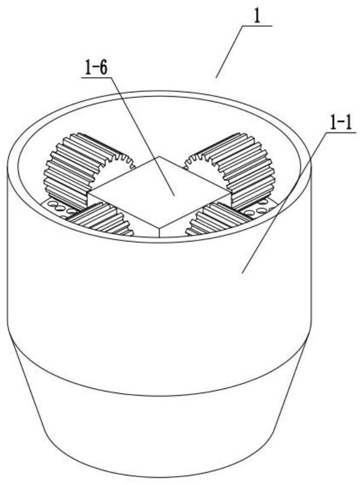
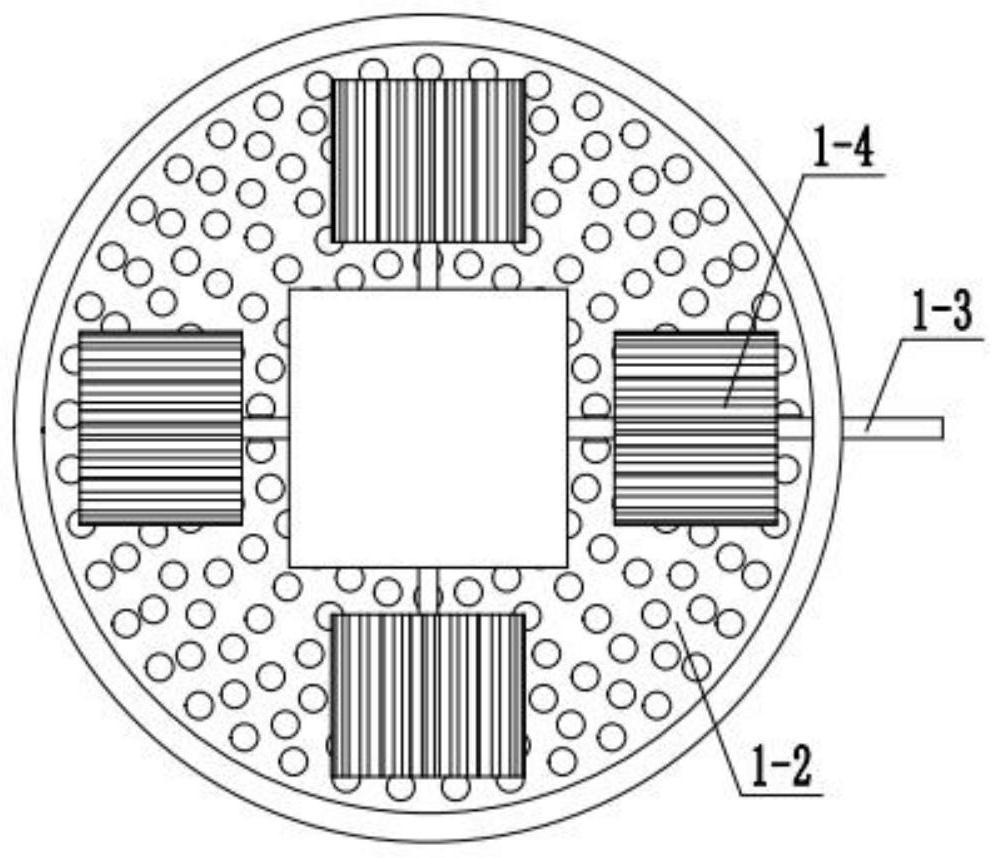
[0033] Combine below Figure 1-14Describe this embodiment, this embodiment will further explain Embodiment 1. The feed assembly 1 includes a feed bucket 1-1, a grinding disc 1-2, a transmission shaft 1-3, a pressure wheel 1-4, and a spur gear 1-5. , chassis 1-6, end face gear 1-7, cutter shaft 1-8, blade 1-9, feed bucket 1-1 is fixedly connected with grinding disc 1-2, feed bucket 1-1 and transmission shaft 1-3 rotate Connection, transmission shaft one 1-3 is fixedly connected with pressure roller 1-4, transmission shaft one 1-3 is fixedly connected with spur gear 1-5, transmission shaft one 1-3 is rotationally connected with chassis 1-6, and spur gear 1- 5 is meshed with the end gear 1-7, the chassis 1-6 is fixedly connected with the grinding disc 1-2, the end gear 1-7 is fixedly connected with the cutter shaft 1-8, and the cutter shaft 1-8 is rotationally connected with the chassis 1-6 , the cutter shaft 1-8 is fixedly connected with the blade 1-9;

[0034] Put the feed in...

specific Embodiment approach 3

[0036] Combine below Figure 1-14 Describe this embodiment. This embodiment will further explain Embodiment 1. The transmission assembly 2 includes a conveyor belt bracket 2-1, a roller 2-2, a conveyor belt 2-3, a transmission belt 2-4, and a transmission shaft 2-2. 5. Cam 2-6, connecting rod 2-7, load-bearing block 2-8, feeding plate 2-9, spring 1 2-10, conveyor belt bracket 2-1 is fixedly connected with feed barrel 1-1, conveyor belt bracket 2-1 Rotately connected with roller one 2-2, roller one 2-2 is connected with conveyor belt 2-3, transmission belt one 2-4 is connected with roller one 2-2, transmission belt one 2-4 is connected with drive shaft two 2- 5 is matingly connected, transmission belt one 2-4 is cooperatively connected with transmission shaft one 1-3, transmission shaft two 2-5 is rotationally connected with conveyor belt support 2-1, transmission shaft two 2-5 is fixedly connected with cam 2-6, and cam 2 -6 is fixedly connected with the connecting rod 2-7, th...


PUM


Abstract

The invention relates to the field of packaging machinery, in particular to feed packaging equipment. A feed assembly is used for producing feed particles, a conveying assembly is used for vibrating and scattering the produced particles, a first roller is matched with a first transmission belt, so that a cam drives a feeding plate to vibrate, and the feed particles are more dispersed, a packaging assembly fixes a bag through the weight of feed, a first bag bearing plate drives a sliding column to slide, a first rotating rod drives a first clutch and a second clutch to be engaged, then a bag fixing plate fixes the bag, a sealing assembly compresses a fourth spring through a second bag bearing plate, then a third rotating rod drives a gear shaft fixing rod, a third gear shaft is engaged with a fourth gear shaft, and then a second rack drives a clamping plate to seal the bag, and through the weight of loaded feed particles, rotating parts of the equipment are connected, and therefore the manual operability is reduced.

Description

technical field [0001] The invention relates to the field of packaging machinery, in particular to feed packaging equipment. Background technique [0002] When processing feed pellets, the processed pellets cannot be packaged, and secondary manual packaging is required, which wastes manpower and material resources. Contents of the invention [0003] The purpose of the present invention is to provide a kind of feed packaging equipment, which can produce feed granules through feed components. The transmission component is to vibrate and break up the courseware after production. The packaging component fixes the pockets by the weight of the feed. The sealing component is to Pockets are clamped. [0004] The purpose of the present invention is achieved through the following technical solutions: [0005] A feed packaging device includes a feed assembly, a transmission assembly, a packaging assembly, and a sealing assembly. The feed assembly is connected to the transmission as...

Claims


Application Information

Patent Timeline
Patent Type & Authority Applications(China)
IPC IPC(8): B65B1/06B65B43/58B65B61/28B65B63/00B02C19/16B02C18/22B02C18/16B02C18/10B02C7/11B02C7/06
CPCB02C7/06B02C7/11B02C18/10B02C18/16B02C18/2216B02C19/16B65B1/06B65B43/58B65B61/28B65B63/00
Inventor 方瑞喜
Owner 方瑞喜
Features
  • R&D
  • Intellectual Property
  • Life Sciences
  • Materials
  • Tech Scout
  • Unparalleled Data Quality
  • Higher Quality Content
  • 60% Fewer Hallucinations
Learn More