Special self-locking lifting appliance for steel structure

A steel structure and spreader technology, applied in the direction of load hanging components, transportation and packaging, etc., can solve problems such as risk reduction, and achieve the effects of risk reduction, convenient operation, and low manufacturing cost

Active Publication Date: 2021-07-13
XINJIANG SUZHONG CONSTR ENG
View PDF14 Cites 0 Cited by
  • Summary
  • Abstract
  • Description
  • Claims
  • Application Information

AI Technical Summary

Problems solved by technology

[0004] In order to overcome the deficiency in the prior art that steel components need to be manually released from the steel wire rope bound between the lifting point of the component and the hook of the tower crane after the steel component is hoisted in place, the present invention provides a special self-locking hoist for steel structures. The binding connection and unbinding process between the hooks of the lifting equipment are all completed by the staff on the ground, which avoids the risk of construction workers climbing up and down. At the same time, the hanging lock mechanism has a locking effect on the fixed bolt, forming an insurance effect. Reduces the risk that the first tie rod will not be unhooked due to human mishandling of the pull cord

Method used


Image

  • Special self-locking lifting appliance for steel structure
  • Special self-locking lifting appliance for steel structure
  • Special self-locking lifting appliance for steel structure

Examples


Embodiment 1

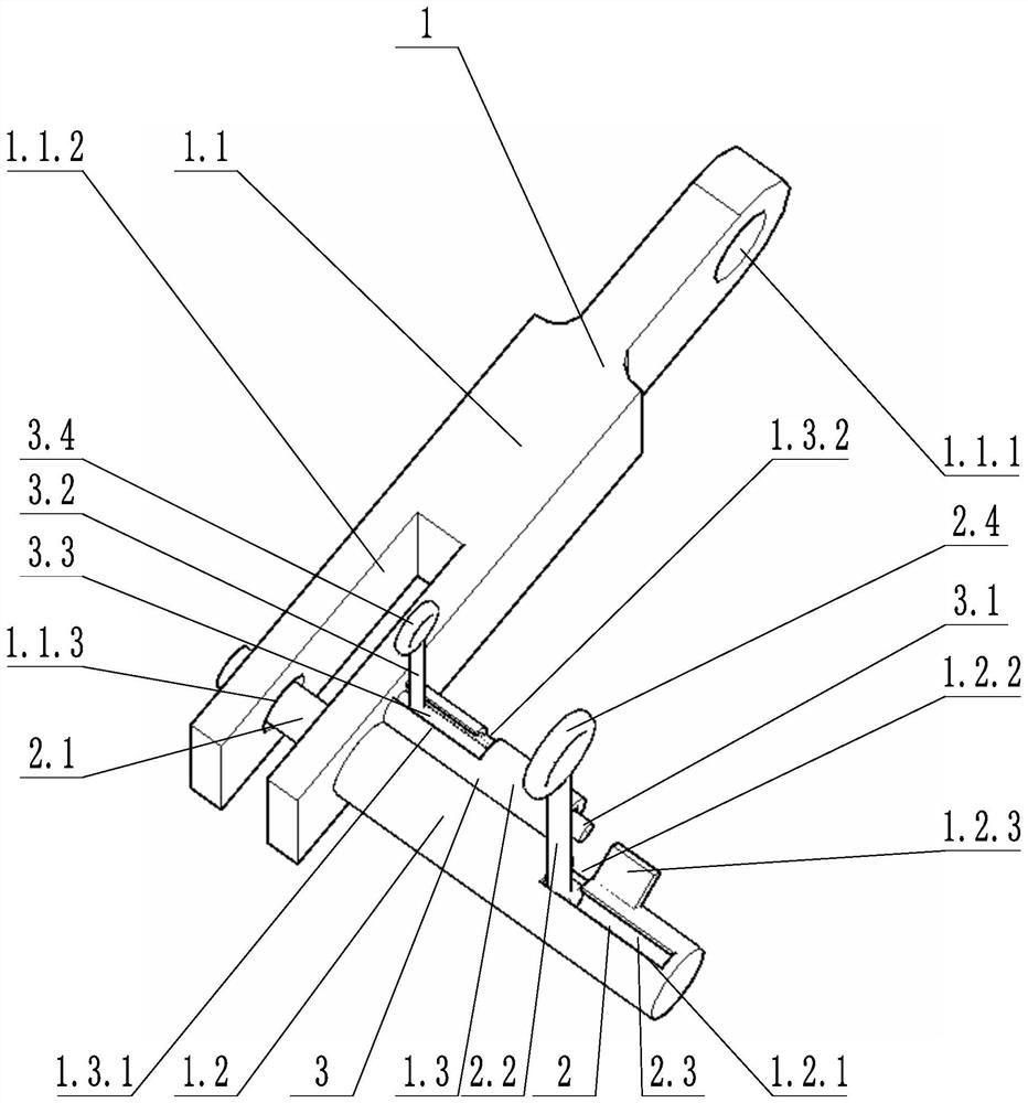
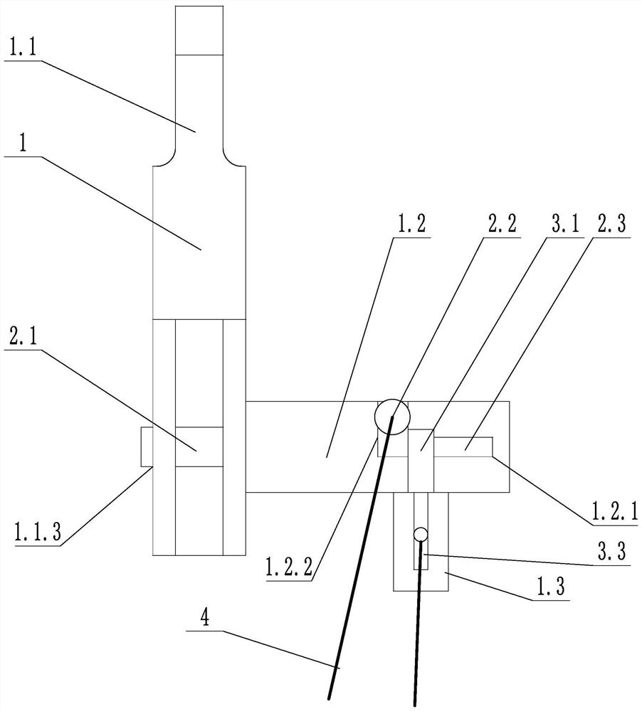
[0031] Such as image 3 As shown, a special self-locking spreader is dedicated to a steel structure, including a spreader body 1, a fixing structure 2, a lock structure 3, and a drawn rope 4, and the spreader body 1 includes a connection block 1.1, a first set of tube 1.2 and the second set. Tube 1.3, the first sleeve 1.2 is perpendicular to the axis of the second sleeve 1.3, and there is a jack 1.1.3 on the connecting block 1.1.3 through the connecting tank 1.1.2, the first set of tube 1.2 The side wall is provided with a first slider 1.2.1 and a first lock groove 1.2.2 in communication.

[0032] The fixing structure 2 includes a fixed latch 2.2, a first lever 2.2 and a first telescopic spring 2.3, and the fixed latch 2.1 is disposed within the first sleeve 1.2 and is slidable with the first sleeve 1.2, and the fixed latch 2.1 can be taken along the first kit 1.2 The axis rotates, one end of the fixed latch 2.3 passes through the jack 1.1.3, and the first telescopic spring 2.3 is ...

Embodiment 2

[0036] Such as figure 1 As shown, a special self-locking spreader is dedicated to a steel structure, including a spreader body 1, a fixing structure 2, a lock structure 3, and a drawn rope 4, and the spreader body 1 includes a connection block 1.1, a first set of tube 1.2 and the second set. Tube 1.3, the connection block 1.1 is provided with a jack 1.1.3, a connecting hole 1.1.1, and a connecting groove 1.1.2, and the jack 1.1.3 pass through the connecting tank 1.1.2, the side wall of the first sleeve 1.2 The first slider 1.2.1 and the first lock slot 1.2.2 are provided with each other; the second lock slot 1.3.1 and the second lock slot 1.3.2 are provided on the side wall of the second sleeve 1.3. .

[0037] The fixing structure 2 includes a fixed latch 2.2, a first lever 2.2 and a first telescopic spring 2.3, and the fixed latch 2.1 is disposed within the first sleeve 1.2 and is slidable with the first sleeve 1.2, and the fixed latch 2.1 can be taken along the first kit 1.2 The...

Embodiment 3

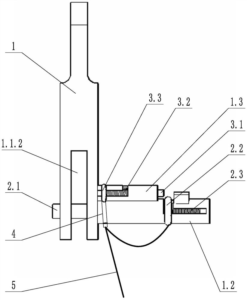
[0041] Such as figure 1 with figure 2 As shown, on the basis of Example 2, the first thus rod 2.2 and the second tilt rod 3.2 are connected to the same roof 4; the second pulley 3.2 is provided with an elastic telescopic member 5, one end and the second end of the elastic scratch piece 5. The tensive rod 3.2 is connected, and one end of the drawing cord 4 is fixed to the elastic telescopic member 5 and connected to the first lever 2.2.

[0042] In the above technical solution, the elastic telescopic member 5 may be a telescopic spring or an elastic elastic rope or other elastic member. One end of the drawstring 4 is bound to the first thus rod 2.2, and the elastic scaling member 5 that is then tied to the second tilt rod 3.2 after the appropriate margin is left. The action of the elastic scratzer 5 is to adjust the length of the rope between the two tie rods and give the second tilt rod 3.2 a certain axial buffer to avoid small do not operate. When you need to unlock, pull the dra...


PUM


Abstract

The invention discloses a special self-locking lifting appliance for a steel structure. The special self-locking lifting appliance comprises a lifting appliance body, a fixing structure, a lifting locking mechanism and a pull rope, wherein the lifting appliance body comprises a connecting block and a first sleeve, an inserting hole and a connecting hole are formed in the connecting block, and a first sliding groove and a first locking groove which communicate with each other are formed in the side wall of the first sleeve; the fixing structure comprises a fixing bolt, a first pull rod and a first telescopic spring, and the fixing bolt is arranged in the first sleeve and is in sliding connection with the first sleeve; the lifting locking mechanism comprises a sliding block, a third telescopic spring and an extension block, the sliding block is in sliding connection with the connecting block, one end of the extension block is fixed to the sliding block, the other end of the extension block is provided with a first locking block, and the first locking block makes contact with the first pull rod; and the first pull rod is connected with the pull rope. According to the special self-locking lifting appliance for the steel structure, the risk that a constructor climbs up and down is avoided, meanwhile, the lifting locking mechanism has a locking effect on the fixing bolt, and then the phenomenon that the first pull rod is unhooked due to manual misoperation of the pull rope is avoided.

Description

Technical field [0001] The present invention relates to the field of engineering construction, in particular, involving a special self-locking spreader for steel structures. Background technique [0002] During the construction of traditional steel structure, steel columns and steel walls generally use each three-layer installation, the single steel member is high, the cross section is long; when the steel member is lifted, it is necessary to rely on the components Point wire rope that is tied between the tower hanging hook. Since this process does not have a safe climb for construction personnel vertical, the construction personnel use the original climbing method, and after connecting the strap on the hook, step on the steel member on the steel member. Column, since the height of a single member exceeds 9 meters, due to the risk of fatigue or lenders from the height of the rope during the climbing process, the tools used in the process of solving the wire rope may cause the too...

Claims


Application Information

Patent Timeline
Patent Type & Authority Applications(China)
IPC IPC(8): B66C1/10
CPCB66C1/10
Inventor 顾李平曹国军白小松
Owner XINJIANG SUZHONG CONSTR ENG
Why Eureka
Try Eureka