Combined energy dissipation wall for hydraulic engineering

A water conservancy engineering and combined technology, applied in water conservancy engineering, sea area engineering, coastline protection, etc., can solve the problems of large interaction stress, long stilling pool, high cost, etc., achieve automatic cleaning, improve energy dissipation efficiency, improve The effect of stability

Active Publication Date: 2021-07-13
王洋
View PDF8 Cites 2 Cited by
  • Summary
  • Abstract
  • Description
  • Claims
  • Application Information

AI Technical Summary

Problems solved by technology

[0002] Water conservancy energy dissipation is one of the problems that must be solved in the application of water conservancy projects. The usual energy dissipation method is to set up stilling pools, stilling sills, energy dissipation walls, etc. downstream of water retaining buildings to promote water flow within a limited range to generate water. The excess energy is consumed through the internal friction, aeration and impact of the water flow. The above method can also be used for the energy dissipation box structure of the pressure pipeline of the irrigation project and the water supply project, but these methods have certain disadvantages.
On the one hand, the energy that can be eliminated by using the hydraulic jump phenomenon is very limited. After the water flow on the front surface of the energy dissipation wall hits the performance wall, the mainstream will reflect or turn back in a certain direction. The stilling pool is long and the project volume is large. The cost is high, and at the same time, the water flow directly collides with the energy-dissipating wall, the interaction stress is large, and the damage to the water-facing surface of the energy-dissipating wall is serious, and it cannot fully apply the energy of the water flow itself. More powerful performance methods to dissipate energy

Method used


Image

  • Combined energy dissipation wall for hydraulic engineering
  • Combined energy dissipation wall for hydraulic engineering
  • Combined energy dissipation wall for hydraulic engineering

Examples


Embodiment 2

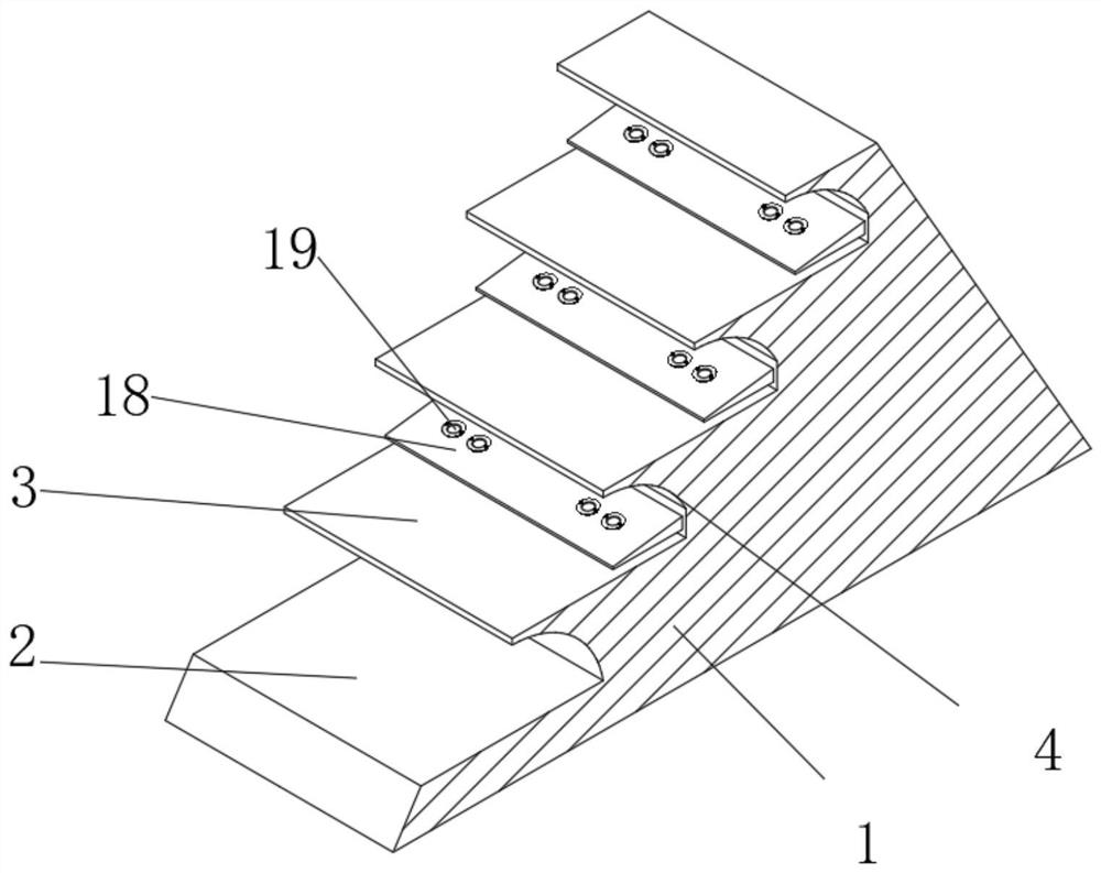
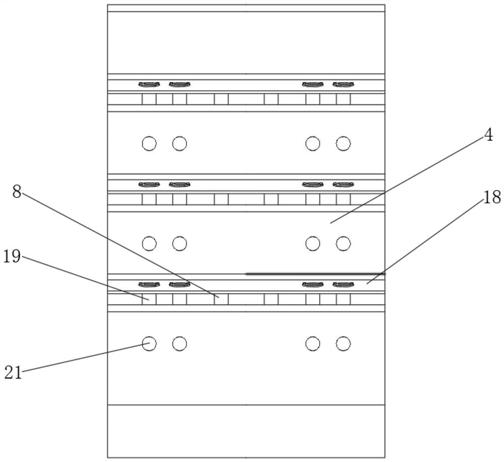
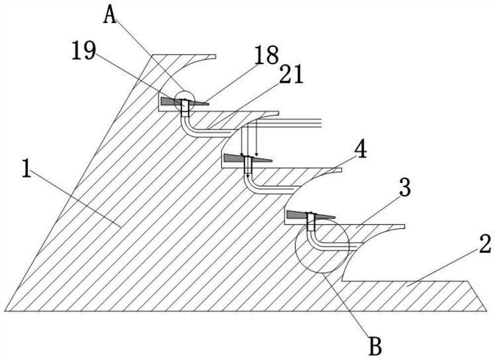
[0035] Because often there are sundries such as branches and plastic garbage floating on the water surface, these sundries often enter in the diversion groove 21 through the moving pipe 19 with the water flow, causing the diversion groove 21 to be blocked, so that the water flow cannot pass through the diversion groove 21. It flows out and flushes the water outside the diversion groove 21; therefore, the blocked sundries will weaken the effectiveness of the device on the water flow, so the device has been further improved.

[0036] Such as Figure 9 As shown, the bottom end of the moving tube 19 is movably socketed in the diversion groove 21. When the water impacts on the buffer plate 18, the buffer plate 18 will go down after being pressured, and at the same time, it will drive the moving tube 19 above it to move downward. At this time, the damping spring 10 will be compressed; when the pressure of the water on the buffer plate 18 disappears, the damping spring 10 resumes its...


PUM


Abstract

The invention belongs to the technical field of hydraulic engineering, and discloses a combined energy dissipation wall for hydraulic engineering. The combined energy dissipation wall for hydraulic engineering comprises a wall body, wherein a mounting groove is formed in the wall body, four auxiliary oil cylinders are fixedly mounted at the bottom of an inner cavity of the mounting groove, a base is fixedly mounted at the tops of the auxiliary oil cylinders, a main oil cylinder is fixedly mounted at the top of the base, and a limiting ring is fixedly mounted on the outer surface of the top of the main oil cylinder. According to the combined energy dissipation wall for hydraulic engineering, when oncoming impact water impacts a cambered surface wall through the cambered surface wall, the flowing direction of the oncoming impact water can be changed, the flowing direction of the oncoming impact water can be changed, the oncoming impact water flows downwards, the oncoming impact water directly impacts the inclined surface of a buffering plate, and the buffering plate moves downwards under pressure, so that a damping spring and a hydraulic mechanism which are lowered are driven to buffer water pressure, impact energy of water energy is partially converted into heat energy and elastic potential energy of the damping spring, then partial energy of water flow is converted, and the energy is counteracted.

Description

technical field [0001] The invention belongs to the technical field of water conservancy engineering, in particular to a combined energy-dissipating wall for water conservancy engineering. Background technique [0002] Water conservancy energy dissipation is one of the problems that must be solved in the application of water conservancy projects. The usual energy dissipation method is to set up stilling pools, stilling sills, energy dissipation walls, etc. downstream of water retaining buildings to promote water flow within a limited range to generate water. The excess energy is consumed through the internal friction, aeration and impact of the water flow. The above method can also be used for the energy dissipation box structure of the pressure pipeline of the irrigation project and the water supply project, but these methods have certain disadvantages. On the one hand, the energy that can be eliminated by using the hydraulic jump phenomenon is very limited. After the water...

Claims


Application Information

Patent Timeline
Patent Type & Authority Applications(China)
IPC IPC(8): E02B8/06
CPCE02B8/06Y02E10/20
Inventor 王洋詹鹏飞田鹏翼梁俸凯王卓黄彦洁任欣吴永娜
Owner 王洋
Why Eureka
Try Eureka